Q170226E01.pdf - 第85页
RH5 4.1 Inspection Check List SERVICE MANUAL 4.1−2 DA3SEC−80−020−B0 4.1.1 XY T able [2] Ball screw [1] LM guide (3) Link pivot [2] Ball screw Inspection Period Inspection item Daily x Make sure that the parallelism of th…

4.1 Inspection Check List
SERVICE MANUAL
RH5
4.1−1
DA3SEC−80−020−B0
4.1 Inspection Check List
DA3SEC−80−020−B0
Sentence No.
This chapter explains routine inspection for keeping your RH5 in proper working condition.
x This chapter is composed of the chief maintenance work, namely “Inspection” and “Lubrication”.
x The drawings used in this technical guide employ a code consisting of numbers and symbols so that you
can see at a glance the location of the part to be lubricated and the type of lubricate to be used. The code
is a s described below. As for the period of the lubrication, as a guide, setting is as follows; 20 hours for
one day, 6 days for one week, 25 days for one month.
()−−−−−Machine oil
[]−−−−−Grease
−−−−−Thelocation of the part not to be lubricated.
Ex. (1)−−−−−Indicates that “part (1) is to be lubricated with machine oil.”
[2]−−−−−Indicates that “part [2] is to be lubricated with grease.”
=REFERENCE=
Refer to “Sensor Layout” for details of the sensor positions.
RH5
4.1 Inspection Check List
SERVICE MANUAL
4.1−2
DA3SEC−80−020−B0
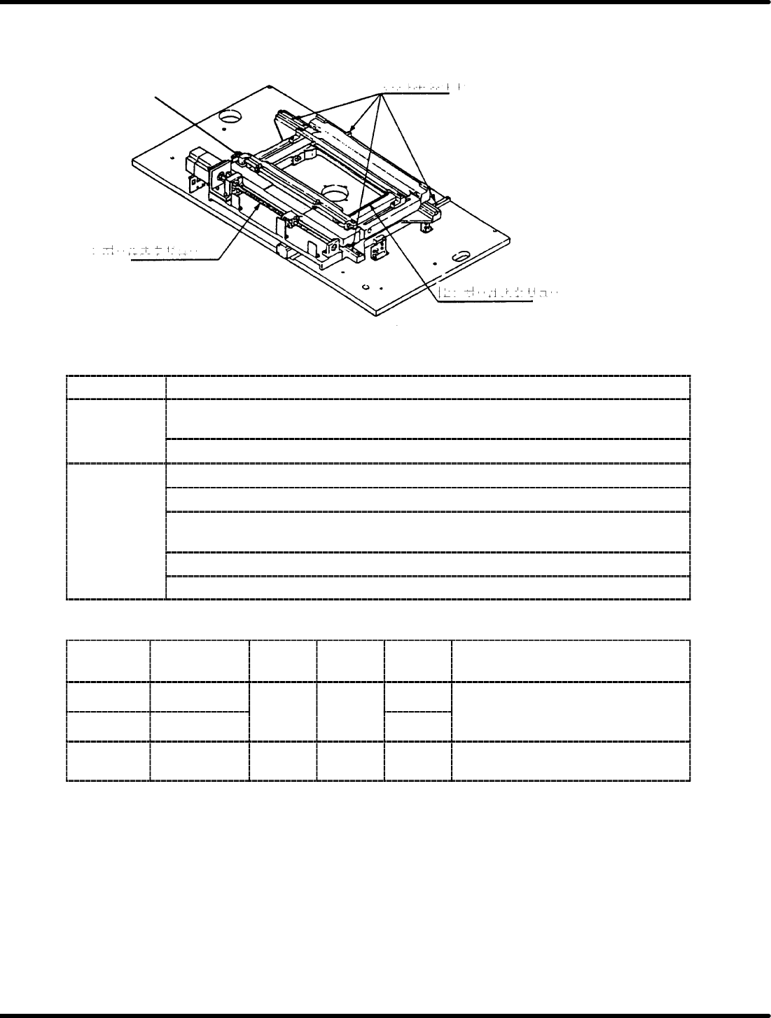
4.1.1 XY Table
[2] Ball screw
[1] LM guide
(3) Link pivot
[2] Ball screw
Inspection
Period Inspection item
Daily
x Make sure that the parallelism of the positioning pin is within the range of
standard value.
Daily
x Make sure that the movement in XY−direction is smooth.
x Make sure that dust is not adhering to the XY axis LM guide.
x Make sure that dust does not build up in the guide rail slot.
Weekly
x Make sure that width of the guide rail is 0.5−1mm wider than the PCB to be
used.
x Make sure that dust is not adhering on the base.
x Make sure that positioner lever is smooth.
Oiling
Part
number
Oiling point Oil type
Oil
volume
Period Lubrication method
[1] LM guide
Grease
Moder−
ate
Weekly
x Remove all dirt adhering on the
surface
completely
and
apply
a
[2] Ball screw
G
rease
a
t
e
amount
Monthly
sur
f
ace comp
l
e
t
e
l
yan
d
app
l
ya
thin coat of grease.
(3) Link pivot
Machine
oil
1−2
drops
Weekly
x Apply 1 or 2 drops on the sliding
surface.
4.1 Inspection Check List
SERVICE MANUAL
RH5
4.1−3
DA3SEC−80−020−B0
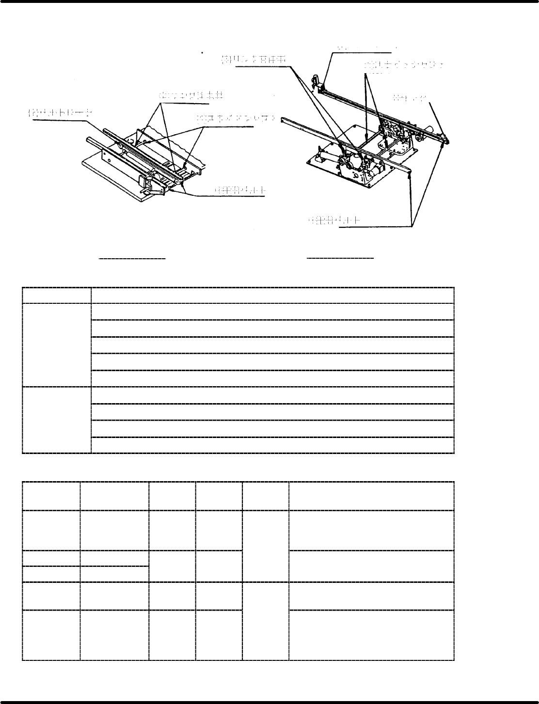
4.1.2 Loader/Unloader
(2) Belt roller
[1] Slide shaft
(2) Belt roller
(3) Link pivot
[1] Slide shaft
(3) Link pivot
NM−8244A/B/C
NM−8245A/B/C
U Conveyor belt
U Conveyor belt
U Sensor
Inspection
Period Inspection item
x Make sure that the belt is not worn or damaged.
x Make sure that lubricant or dust is not adhering to the belts.
Daily x Make sure that belt tension is properly adjusted.
x Make sure that width of the rail is 0.5 − 1 mm wider than the PCB to be used.
x Make sure that PCB transfer is smooth.
x Make sure that all rollers turn.
W
eekly
x Make sure that belts do not slip.
W
ee
kl
y
x Make sure that stoppers function properly.
x Make sure that the loader and unloader width adjust movements are smooth.
Oiling
Part
number
Oiling point Oil type
Oil
volume
Period Lubrication method
[1] Slide shaft Grease
Moder−
ate
amount
Monthl
y
x Remove all dirt adhering on the
surface and apply a thin coat of
grease.
[2] Belt roller
Machine 1−2
Monthly
x
App
l
y
1or2dro
p
s on the slidin
g
(3) Link pivot
Machine
oil
12
drops
Apply
1
or
2
drops
on
the
sliding
surface.
Sensors
x Make sure that lubricant does not
come in contact with sensors.
Conveyor belt
Daily
x Make sure that lubricant does not
come in contact with belt surfaces
or places that come in contact
with the belts.