Q170226E01.pdf - 第302页
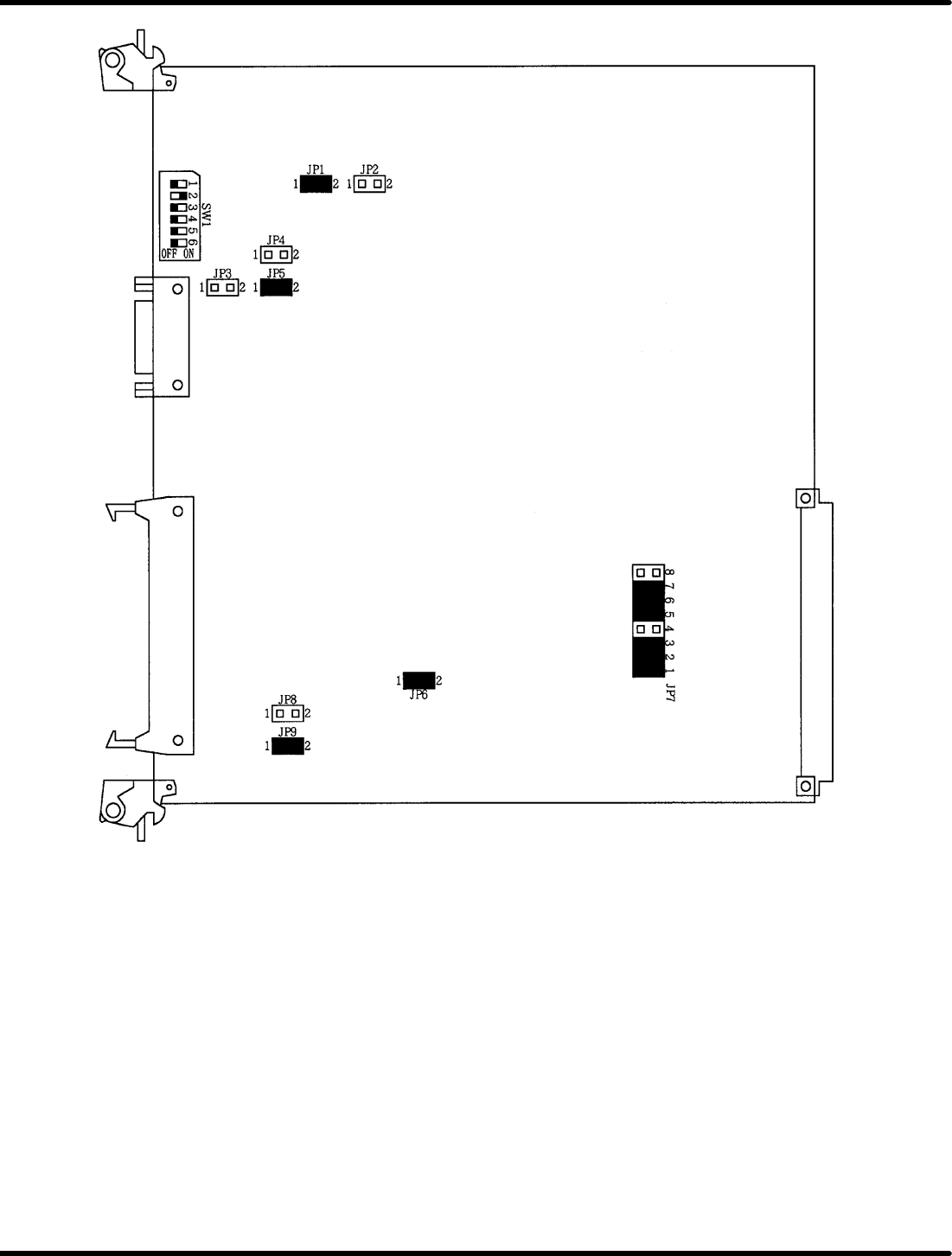
8.3 List of Jumper Switch Settings SERVICE MANUAL RH5 8.3−5 DA3SEC−85−540−B0 General−purpose input switch on the main side − JP9, 10 Permits leading from main PIO. ON: 0, OFF: 1 Not used General−purpose switch 1 2 3 4 56…
RH5
8.3 List of Jumper Switch Settings
SERVICE MANUAL
8.3−4
DA3SEC−85−540−B0
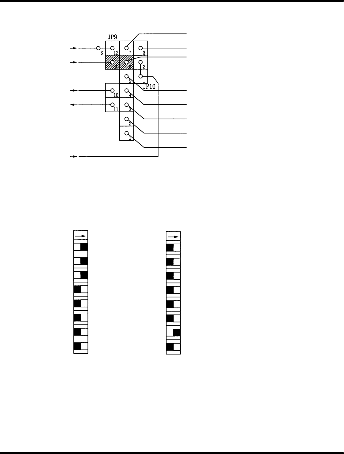
Bus interrupt I/O setting − JP9, 10
* INTL
* MBINT
* ERROR
* INT2IN
* INTH
* INT6
* INT7
* INT5
* INT4
* INT3
* INT2
* INT1
* INT0
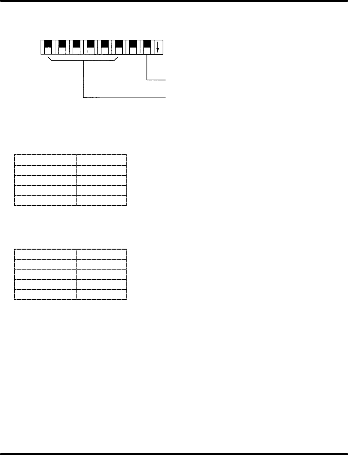
CNC board address setting switch − DSW2, 3
Permits base address setting on P2 bus of this board.
* AD10
* AD11
* AD12
* AD13
* ADR20
* ADR21
* ADR22
* ADR23
DSW2 DSW3
ON ON
Address in the above setting is for
74000H.
8
7
6
5
4
3
2
1
8
7
6
5
4 * ADRC
3 * ADRD
2 * ADRE
1 * ADRF
8.3 List of Jumper Switch Settings
SERVICE MANUAL
RH5
8.3−5
DA3SEC−85−540−B0
General−purpose input switch on the main side − JP9, 10
Permits leading from main PIO. ON: 0, OFF: 1
Not used
General−purpose
switch
1 23 45678
ON
Offset adjusting volume − VRB1 to 4
Enables adjustment of command output voltage offset.
Volume
Axis
VRB1 1st axis
VRB2 2nd axis
VRB3 3rd axis
VRB4 4th axis
Gain fine−adjusting volume − VRA1 to 4
Gain can be fine−adjusted around the setting voltage 1 (command output voltage).
Gain
Axis
VRA1 1st axis
VRA2 2nd axis
VRA3 3rd axis
VRA4 4th axis
RH5
8.3 List of Jumper Switch Settings
SERVICE MANUAL
8.3−6
DA3SEC−85−540−B0
CPU−286E (I)−12 No. 9981