Q170226E01.pdf - 第356页
8.6 Checking Slow Down, Origin, Limit and Safety Limit Sensors SERVICE MANUAL RH5 8.6−1 DA3SEC−85−500−A0 8.6 Checking Slow Down, Origin, Limit and Safety Limit Sensors DA3SEC−85−500−A0 Sentence No. Procedure 1. Select “M…

RH5
8.5 Cycle Timer Setting
SERVICE MANUAL
8.5−4
DA3SEC−85−490−B0
= MEMO =
8.6 Checking Slow Down, Origin, Limit and Safety Limit Sensors
SERVICE MANUAL
RH5
8.6−1
DA3SEC−85−500−A0
8.6 Checking Slow Down, Origin, Limit and Safety Limit
Sensors
DA3SEC−85−500−A0
Sentence No.
Procedure
1. Select “MONITORING” on the operation screen.
2. Select “MEMORY” on the monitoring screen.
3. Select “CNC” (X/Y/Z axis).
4. Input an address of the axis to be checked.
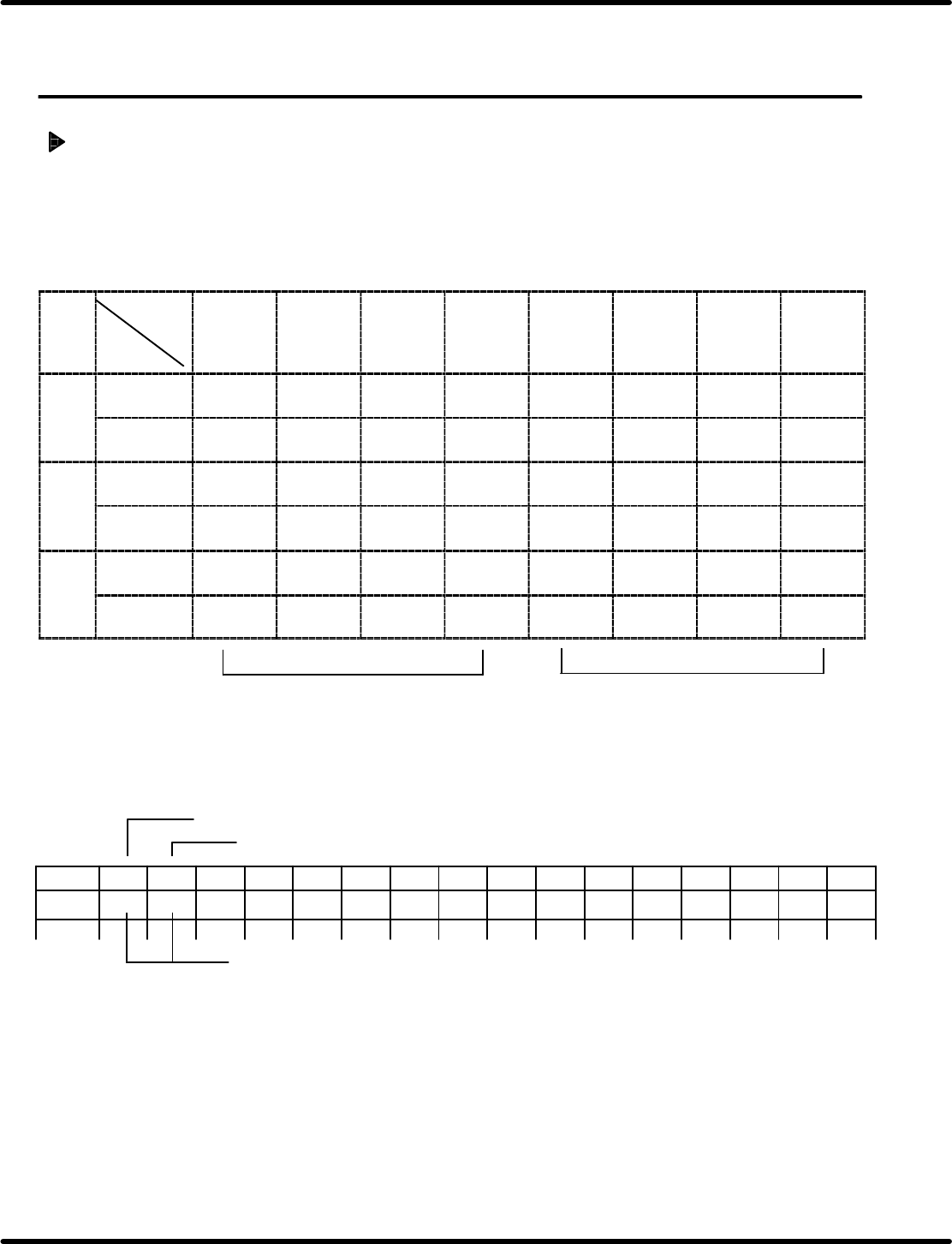
Bit (hexa−
decimal)
Address
7
(8)
6
(4)
5
(2)
4
(1)
3
(8)
2
(4)
1
(2)
0
(1)
Xaxis 84189 Origin
sensor
+ limit − limit Slow
down
Interlock Motor
origin
8148A − safety
limit
+ safety
limit
Yaxis 86189 Origin
sensor
+ limit − limit Slow
down
Interlock Motor
origin
8618A − safety
limit
+ safety
limit
Zaxis 88189 Origin
sensor
+ limit − limit Slow
down
Interlock Motor
origin
8818A − safety
limit
+ safety
limit
Tens
Ones
Ex. To check the X axis:
Choose “CNC” from the memory on the monitoring screen to input “84189”.
Monitoring screen
Address “84189”
Address “8418A”
Check here. (Displayed in two−digits hexadecimal )
Address
0123456789ABCDEF
84189
(1) (2)

RH5
8.6 Checking Slow Down, Origin, Limit and Safety Limit Sensors
SERVICE MANUAL
8.6−2
DA3SEC−85−500−A0
(Displayed example)
a. Only when origin sensor is turned ON: “40” appears in (1).
b. Only when slow down sensor is turned ON.: “08” appears in (1).
c. Only when + limit is turned ON: “20” appears in (1).
d. Only when − limit is turned ON: “10” appears in (1).
e. Only when + safety limit is turned ON: “01” appears in (2).
f. Only when − safety limit is turned ON: “04” appears in (2).
(When duplicate data is input:)
When a and b are turned ON: “48” appears in (1).
When a, b and c are turned ON: “68s” appears in (1).