Q170226E01.pdf - 第214页
T ape waste Cut state 10.2 mm H 0.2 5.34 A x i s H eight Check and Adjustment SERVICE MANUAL RH5 5.34−1 DA3SEC−83−9S0−A0 5.34 A x i s H e i g h t C heck and Adjustment DA3SEC−83−9S0−A0 Sentence No. When to perform x When…

RH5
5.33 Lead Cutter and Tape Cutter Stroke Adjustment
SERVICE MANUAL
5.33−4
DA3SEC−83−9R0−A0
= MEMO =
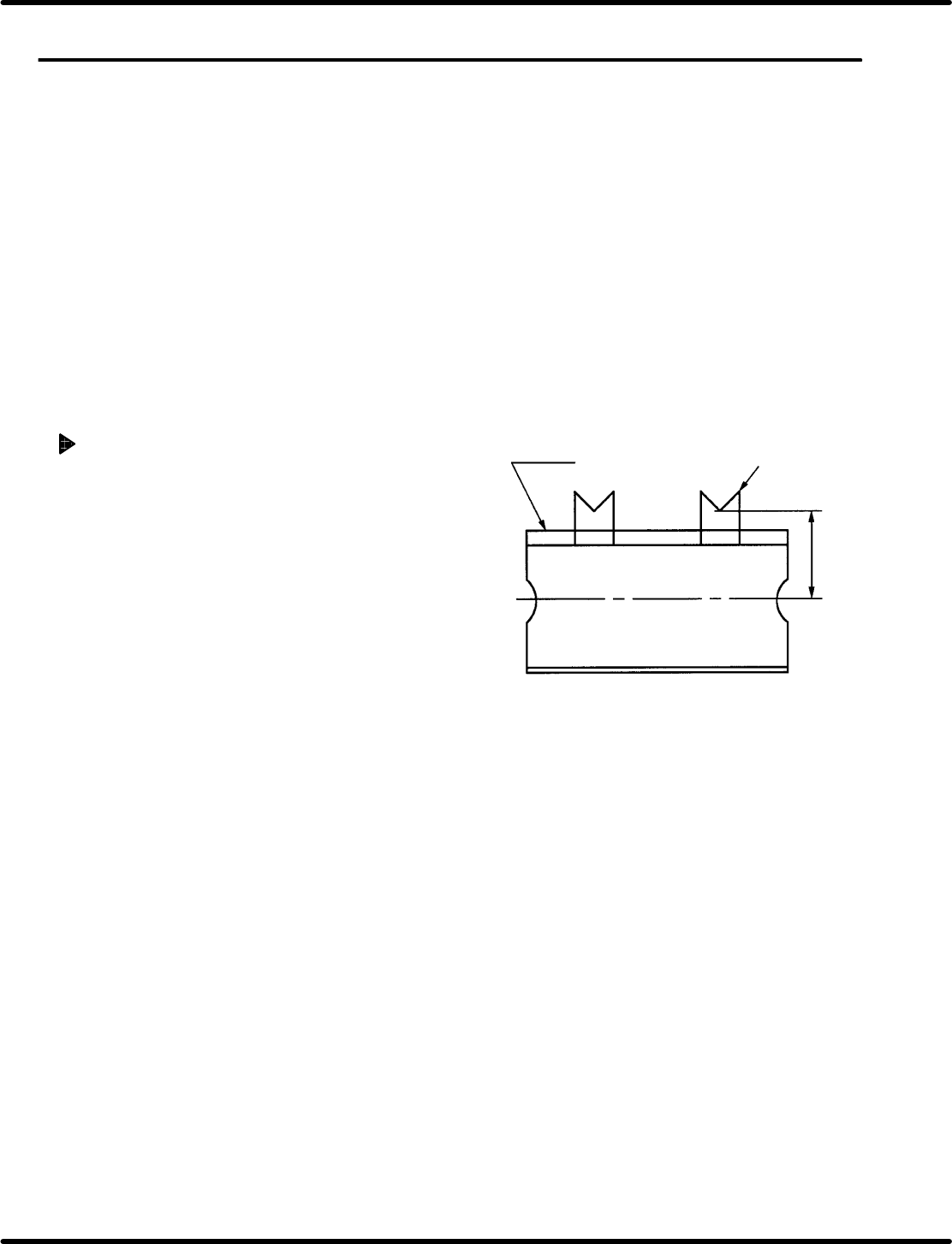
Tape waste
Cut state
10.2 mm H 0.2
5.34 Axis Height Check and Adjustment
SERVICE MANUAL
RH5
5.34−1
DA3SEC−83−9S0−A0
5.34 Axis Height Check and Adjustment
DA3SEC−83−9S0−A0
Sentence No.
When to perform
x When tape wastes are scattered even
after replacing the lead cutter and tape
cutter.
x When insertion errors occur frequently.
Preparation
x Allen wrench
x Thickness gauge
x Spanner
x Slotted screwdriver
Tape waste check
1. In AUTO mode, insert components and
check the lead wastes.
2. Make sure that tape waste is
10.2r0.2 mm in length.
=CHECK=
Cut tape waste on both sides of the
Z axis and check it.
(Z axis Nos. 1 and 80 (62))
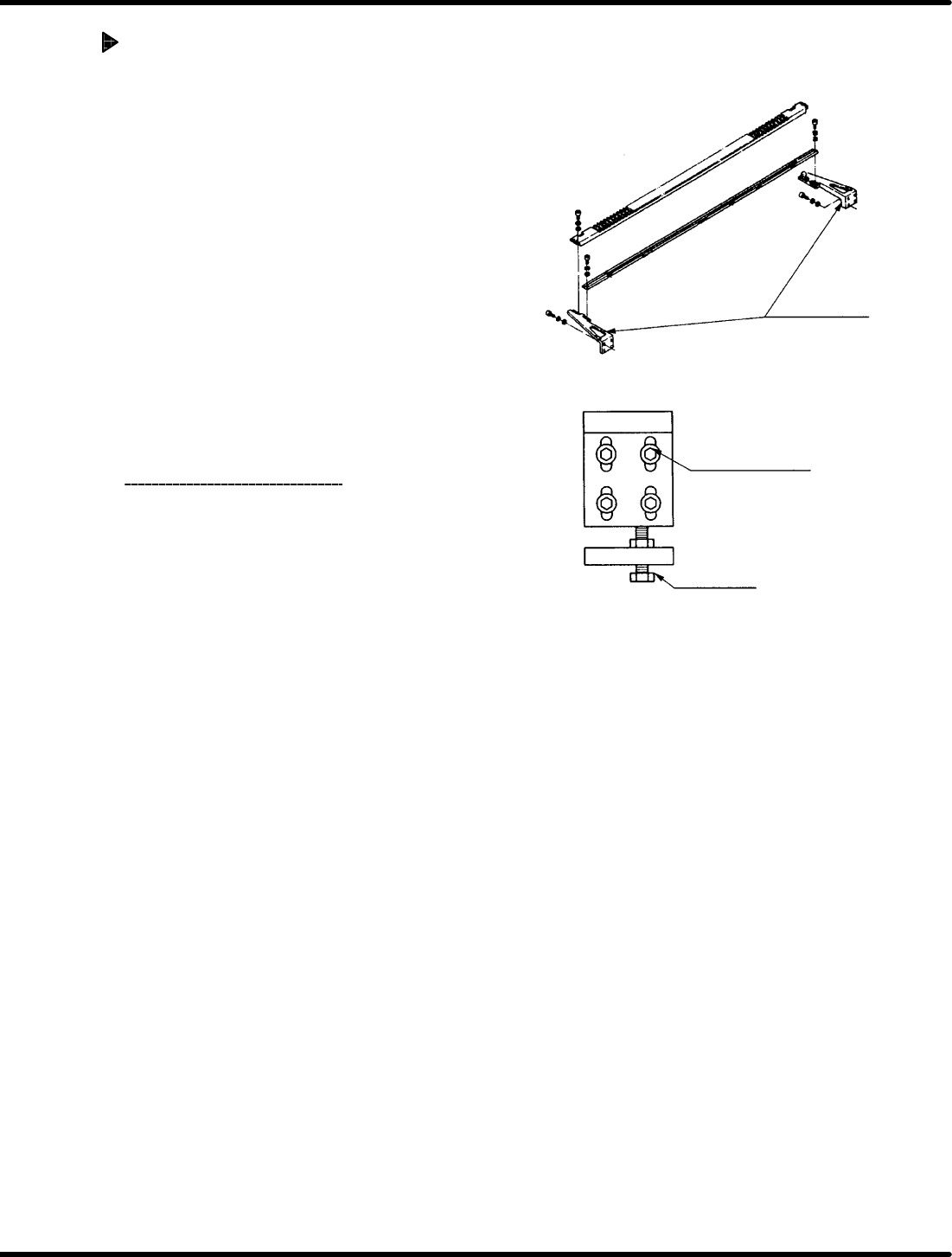
Z axis holder
bracket
Z axis holder bracket
(4−M8)
Bolt stopper
Two points at the Z axes Nos. 1 and 80 (62)
RH5
5.34 Axis Height Check and Adjustment
SERVICE MANUAL
5.34−2
DA3SEC−83−9S0−A0
Adjusting Z axis height (Raising
the Z axis)
1. Disengage the Z axis holder bracket (4− M8).
2. Using a slotted screwdriver, lift the Z axis
holder bracket and sandwich the thickness
gauge (has the height to be raised)
between the bolt stopper and holder
bracket.
3. Retighten the Z axis holder bracket (4− M8).
4. Remove the thickness gauge and loosen
the bolt stopper.
5. Squeeze the bolt stopper and secure it so
that 0.03 mm thickness gauge will not be
fit in.
6. Check the tape waste
again.