Q170226E01.pdf - 第333页
RH5 8.3 List of Jumper Switch Settings SERVICE MANUAL 8.3−36 DA3SEC−85−540−B0 (2) Interrupt The multibus interrupt lines are used on this board as described in the following. INT3: The NMI interrupt on this board occurs …
8.3 List of Jumper Switch Settings
SERVICE MANUAL
RH5
8.3−35
DA3SEC−85−540−B0
Multibus interface
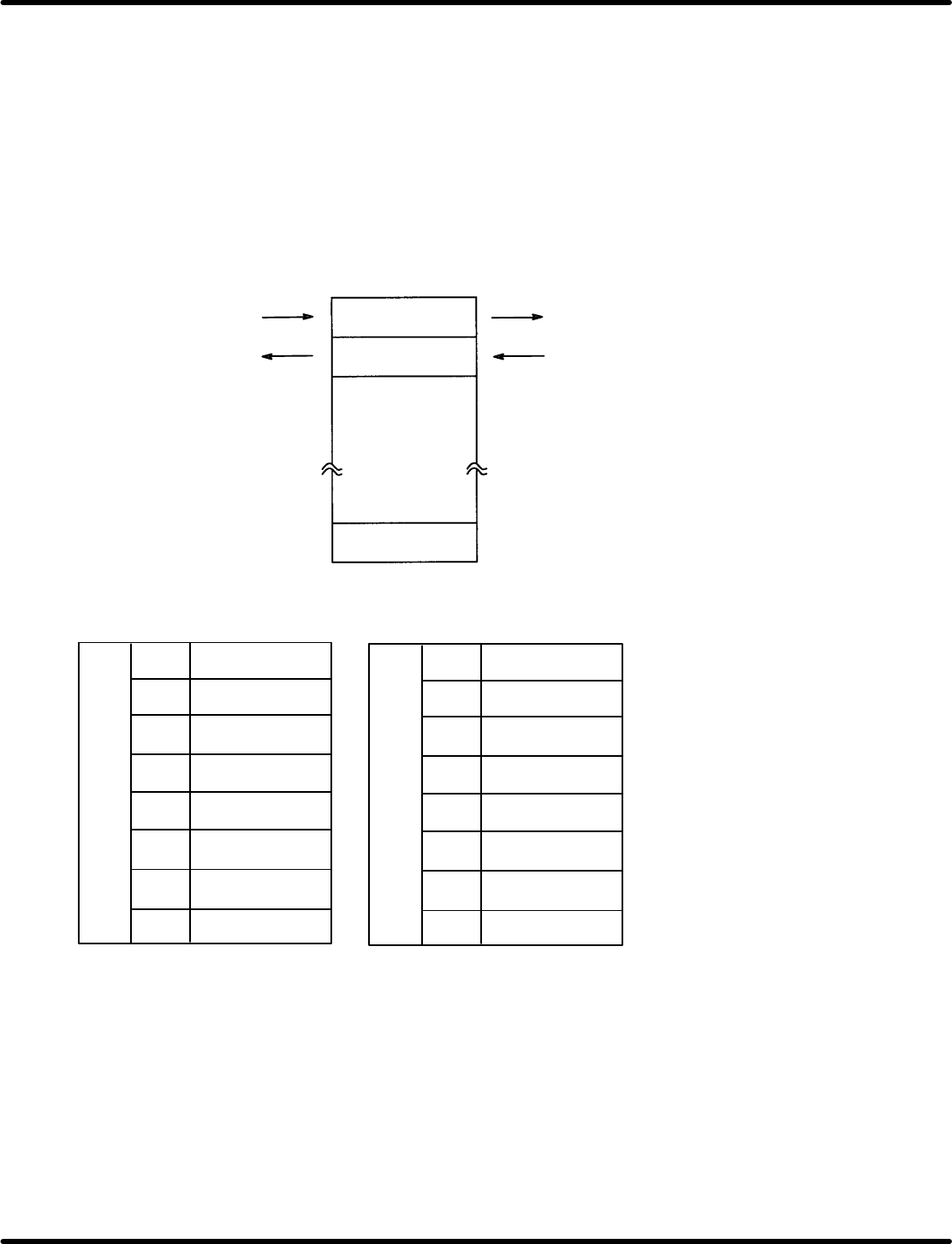
(1) Dual port RAM
This board cannot directly access to the multibus. (slave mode only).
Communications with the main CPU can be done passing through the dual port RAM on this board. It
is possible to send the interrupt notification to the main CPU through the multibus interrupt line, by
writing the interrupt into the 7FE address (offset address) from the MPU (64180) on this board.
This factor will be released by reading−out the same address on the main CPU.
Similarly, the interrupt will be notified through INT0 of the MPU on this board, by writing the interrupt
into the 7FF address from CPU. This factor will be released by reading−out the same address on the
internal MPU.
Always bite−access to the host CPU.
For details, see the MB8421 manual.
Host CPU side
Internal CPU side
7FFH
7FEH
000H
The address map seen from the host CPU is set with DIP SW3 and SW4 on the board.
SW3
ON: 1
OFF: 0
ADRF
1
2
3
4
5
6
7
8
ADRE
ADRD
ADRC
ADRB
Not used
Not used
Not used
SW4
ADR23
1
2
3
4
5
6
7
8
ADR22
ADR21
ADR20
AD13
AD12
AD11
AD10

RH5
8.3 List of Jumper Switch Settings
SERVICE MANUAL
8.3−36
DA3SEC−85−540−B0
(2) Interrupt
The multibus interrupt lines are used on this board as described in the following.
INT3: The NMI interrupt on this board occurs as the error interrupt.
INT6: The interrupt occurs on this board as the end interrupt.
INT7: The interrupt is output from this board as the dual port RAM interrupt notification.
Each of the interrupt lines can be used by shorting JP1 (short pin) on this board.
Pin
Interruption
JP1−1 INT0
JP1−2 INT1
JP1−3 INT2
JP1−4 INT3
JP1−5 INT4
JP1−6 INT5
JP1−7 INT6
JP1−8 INT7

8.3 List of Jumper Switch Settings
SERVICE MANUAL
RH5
8.3−37
DA3SEC−85−540−B0
Cycle Timer Setting
CS
Ad-
dress
Name Angle Description
1
00
01
XY Hold
M: 130q
ON timing X/Y axis emergency stop timing
1
00
01
XY
−
H
o
ld
M:
130
LL: 140q
OFF timing X/Y axis start timing
2
00
01
Spare
ON timing
2
00
01
S
pare
OFF timing
3
00
02
Z axis
hold
condition
185 (340
q
)
ON timing Z axis emergency stop timing
3
00
02
Z
−ax
i
s
h
o
ld
con
diti
on
185
−
(340
q
)
OFF timing Z axis start condition
4
00
03
Middle
1
15 155
q
ON timing H axis acceleration effective start
timing
4
00
03
Middle
re−acceleration
1
15
−
155
q
OFF timing H axis acceleration effective stop
timing
5
00
04
T
est
ON timing
5
00
04
T
es
t
OFF timing
6
00
05
Cut waste drop high
275 290
q
ON timing Cut waste drop valve ON timing
0.36/0.29 (sec)
6
00
05
Cut
waste
drop
high
speed
275
−
290
q
OFF timing Cut waste drop valve OFF timing
0.36/0.29 (sec)
7
00
06
Cutter
return
220 310
q
ON timing Used for software debugging (Usually
not used)
7
00
06
C
u
tt
er re
t
urn
220
−
310
q
OFF timing Used for software debugging (Usually
not used)
8
00
07
Cut waste drop low
285 300
q
ON timing Cut waste drop valve ON timing
0.45/0.6 (sec)
8
00
07
Cut
waste
drop
low
speed
285
−
300
q
OFF timing Cut waste drop valve OFF timing
0.45/0.6 (sec)
9
00
10
Origin
358 10
q
ON timing H axis origin ON timing
9
00
10
O
r
i
g
i
n
358
−
10
q
OFF timing H axis origin OFF timing
10
00
1
1
Origin
stop
low
speed
325 10
q
ON timing 0.45/0.6 sec H axis origin stop timing
10
00
1
1
O
r
i
g
i
ns
t
op
l
o
w
spee
d
325
−
10
q
OFF timing −
1
1
00
12
Origin stop medium
310 10
q
ON timing 0.36 sec H axis origin stop timing
1
1
00
12
Origin
stop
medium
speed
310
−
10
q
OFF timing −
12
00
13
Origin stop high
310 10
q
ON timing 0.29 sec H axis origin stop timing
12
00
13
Origin
stop
high
speed
310
−
10
q
OFF timing −
13
00
14
Special stop + guide
290 320
q
ON timing Not used
13
00
14
Special
stop
+
guide
pin change
290
−
320
q
OFF timing Insertion pitch changeover timing
14
00
15
Inching
stop
70 230
q
ON timing Inching 1 stop timing
14
00
15
I
nc
hi
ng s
t
op
70
−
230
q
OFF timing Inching 2 stop timing
15
00
16
Middle stop + part
190 320
q
ON timing Part exhaust check timing
15
00
16
Middle
stop
+
part
exhaust
190
−
320
q
OFF timing X/Y/Z axis action error stop timing
16
00
17
PH
error
+
step
start
240 60
q
ON timing Step start timing
16
00
17
PH
error + s
t
ep s
t
ar
t
240
−
60
q
OFF timing PH error detection timing