Q170226E01.pdf - 第141页
RH5 5.13 Insertion Head Insertion Chuck Height Check and Adjustment SERVICE MANUAL 5.13−2 DA3SEC−83−8VO−A0 Adjusting insertion chuck height (When underfeed occurs) 1. Loosen bolt A (x 2) until there is play in the insert…
5.13 Insertion Head Insertion Chuck Height Check and Adjustment
SERVICE MANUAL
RH5
5.13−1
DA3SEC−83−8VO−A0
5.13 Insertion Head Insertion Chuck Height Check and
Adjustment
DA3SEC−83−8VO−A0
Sentence No.
When to perform
x When parts leads do not readily slip
into the guide chuck.
x When insertion errors occur
frequently.
x Allen wrench
x Gap gauge
Required tools
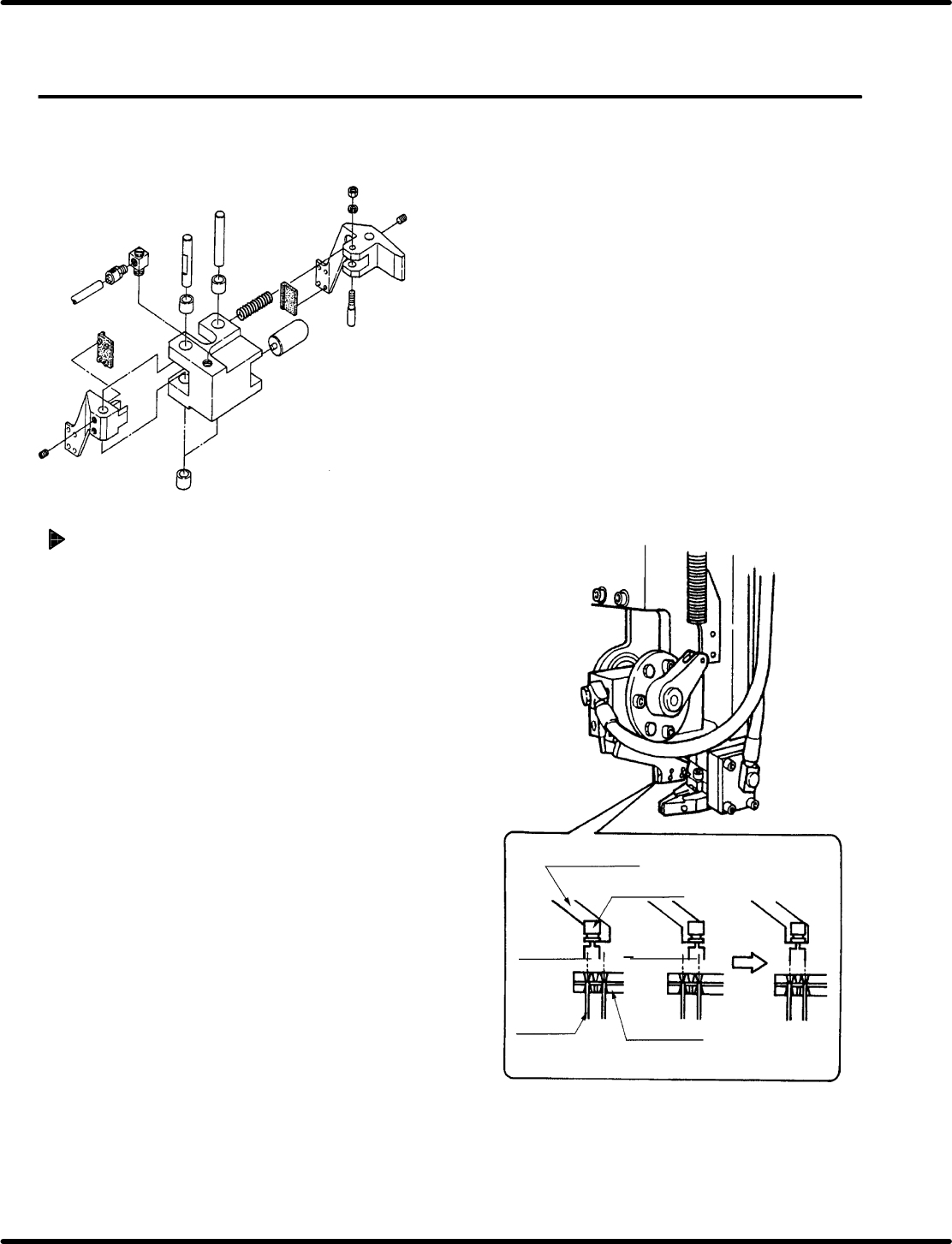
Insertion chuck height check
1. Turn ON the CAM ROTATION ENABLE and
INCHING switches on the sub−control panel in
the SEMIAUTO mode. Perform feeding and
cutting to make sure parts are chucked properly
to the transfer chuck.
2. After making checks, turn the RESET and
BRAKE RELEASE switches ON, rotate the hand
wheel until the digital sequence timer is at
approximately 195q position, and check handover
again.
Insertion chuck
Electronic
component
Underfeed
Overfeed
Guide pin
Guide chuck
(NG) (OK)
RH5
5.13 Insertion Head Insertion Chuck Height Check and Adjustment
SERVICE MANUAL
5.13−2
DA3SEC−83−8VO−A0
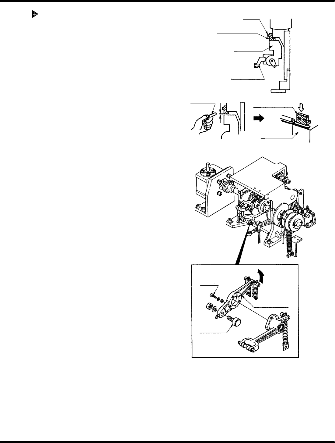
Adjusting insertion chuck height
(When underfeed occurs)
1. Loosen bolt A (x 2) until there is play in
the insertion head upper end stopper.
2. Turn the hand wheel until the cam shaft is
at the 0 q position on the digital sequence
timer, insert a gap gauge the same size
as the discrepancy when the insertion
chuck is in the chucking position,
between the upper stopper and the
insertion head. Without removing the
gauge, tighten bolts A (x 2) until fixing the
stopper in place.
=CHECK=
Fix the upper stopper such that the gap
gauge is flush against both the upper
end stopper and insertion head.
3. Remove the gap gauge and turn the hand
wheel until the cam shaft is at the 90q
position on the digital sequence timer.
4. Loosen bolts B (x 5) from the rear side of
the machine until there is some play in
the insertion head vertical lever.
Bolt A
Upper end stopper
Insertion chuck
Insertion head
Gap gauge
Upper end stopper
Insertion head
Bolt A
Head vertical lever
Cam follower
5.13 Insertion Head Insertion Chuck Height Check and Adjustment
SERVICE MANUAL
RH5
5.13−3
DA3SEC−83−8VO−A0
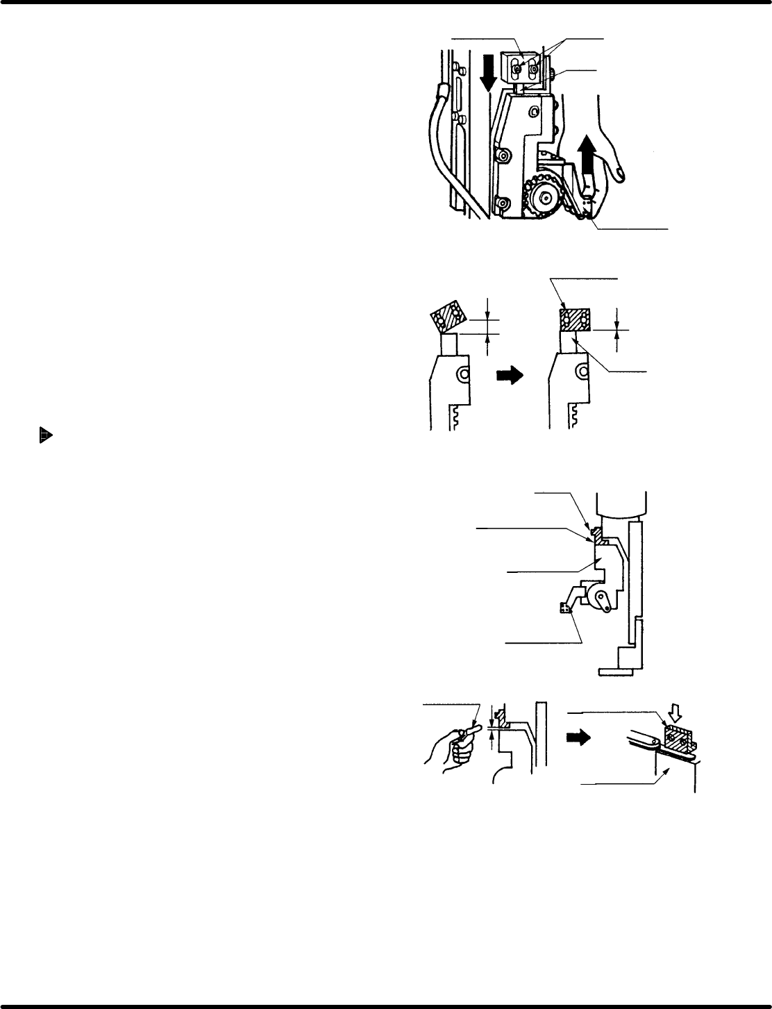
5. Loosen bolts C (x 2) until there is some play in
the rack stopper.
6. Pull the head vertical lever upwards. Raise the
insertion chuck until upper stopper and rack
stopper are flush with one another.
7. In this state, when the gap between the cam and
the cam follower on the head vertical lever is at the
0 position, retighten bolts B (x 5).
8. From the front of the machine, raise the insertion
chuck by hand until contacting the rack stopper .
Then, fix the chuck with bolt C (x 2).
=CHECK=
Make sure the rack and rack stopper are
flush with one another.
9. Turn the hand wheel until the digital sequence
timer is at the 0q position. Check there is no gap
between the upper end stopper and the insertion
head. Also, check insertion chuck height again.
Adjusting insertion chuck height
(When over feed occurs)
1. Turn the hand wheel in the reverse direction
until a gap is opened between the upper end
stopper and the insertion head.
2. Insert a gap gauge the same size as the
discrepancy when the insertion chuck is in the
chucking position, between the upper stopper
and the insertion head. Then, turn the hand
wheel in the normal direction until parts are just
touching the gauge.
3. Check there is no gap between the upper
stopper, gap gauge and insertion head. Remove
the gap gauge and, without changing the
present state, loosen bolt A (x 2) until there is
some play in the upper stopper.
4. Hold the upper stopper against the insetting
head and retighten bolt A (x 2).
Gap
Rack stopper
No gap
Rack
Rack stopper
Bolt C
Rack
Insertion chuck
Upper end stopper
Bolt A
Insertion head
Insertion chuck
Gap gauge
Upper end stopper
Insertion head