Q170226E01.pdf - 第53页
RH5 2.4 Control Configuration SERVICE MANUAL 2.4−4 DA3SEC−82−130−B0 = MEMO =
2.4 Control Configuration
SERVICE MANUAL
RH5
2.4−3
DA3SEC−82−130−B0
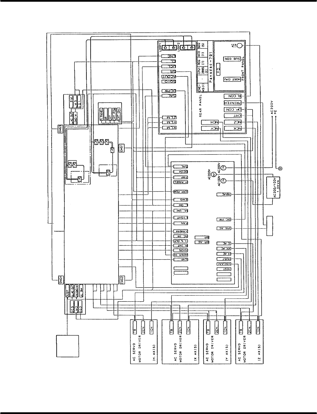
2.4.2 Control System Diagrams
Tape cut
waste
bottle unit
Option UL side
Z motor
Z encoder
X motor
X encoder
Y motor
Y encoder
Hmotor
H encoder
Distortion gauge
Forced−oil value
Interlock key SW
Interlock SW
Recognition light
Fan motor
Handy lamp
Unloader motor
Loader motor
XYZ−axes safety limit SW
Option
Optical module
(Upper base unit)
Option L side
Cam encoder
Main control panel
Power source unit
Down
transfer
Printer
Factory power source
V acuum
Power source unit
RH5
RH5
Reserved
Reserved
Reserved
Reserved

RH5
2.4 Control Configuration
SERVICE MANUAL
2.4−4
DA3SEC−82−130−B0
= MEMO =
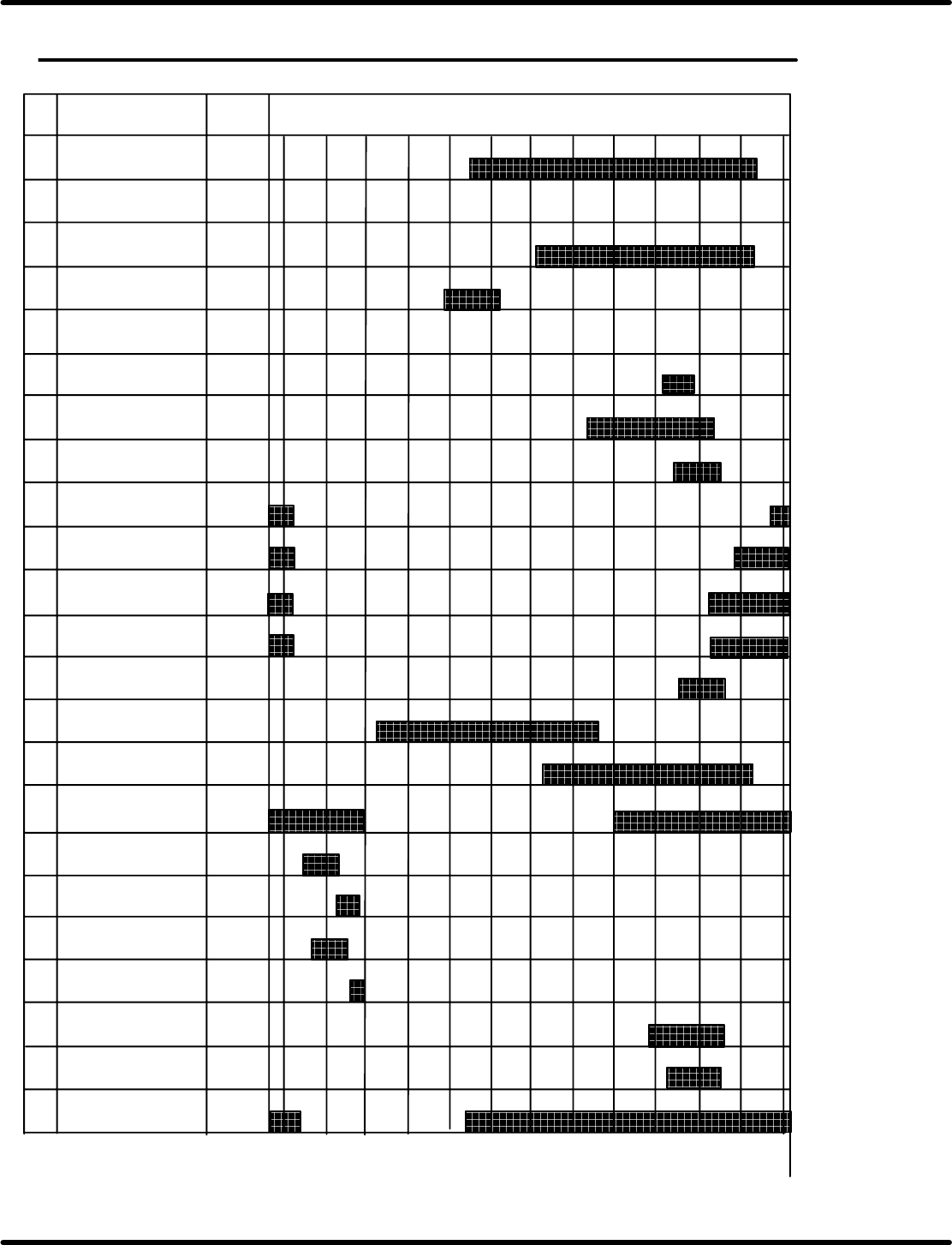
2.5 Cycle Timer Timing Chart
SERVICE MANUAL
RH5
2.5−1
DA3SEC−82−270−A0
2.5 Cycle Timer Timing Chart
DA3SEC−82−270−A0
Sentence No.
XY−Hold
1
CS
Name ADD
2
3
4
5
6
7
8
9
10
11
12
13
14
15
16
17
18
19
20
21
22
23
Z axis hold condition
Intermediate
reacceleration
0000
0001
0002
0003
0004
0005
0006
0007
0010
0011
0012
0013
0014
0015
0016
0017
0020
0021
0022
0023
0024
0025
0026
130q¢140q)*
342q
185q
0G
90G
180G
270G
360G
340q
115q
155q
275q
290q
220q
310q
310q
310q
310q
285q
358q
325q
10q
10q
10q
10q
10q
125q
280q
312q
265q
320q
50q
60q
15q
35q
35q
55q
25q
40q
70q
60q
230q
190q
320q
240q
290q
320q
Cut waste drop
high speed
Cutter return
(For D−SEQ)
Low speed origin
stop
Cut waste drop
low speed
Origin
Medium speed
origin stop
High speed origin
stop
Special stop + guide
pin changeover
Inching stop
Intermediate stop +
component exhaust
PH error + Step
start
Swivel lock
(0.29 s, 0.45 s)
Swivel lock release
(0.29 s, 0.45 s)
Insertion check
timing
Insertion pusher high
pressure
(MANU, 0.45 s, 0.6 s)
Feed condition
Swivel Y dir lock
(0.36 s, 0.6 s)
Swivel lock release
(0.36 s, 0.6 s)