Q170226E01.pdf - 第126页
5.8 Insertion Head Insertion Chuck 90 q Swing Check and Adjustment SERVICE MANUAL RH5 5.8−1 DA3SEC−83−8QO−A0 5.8 Insertion Head Insertion Chuck 90 G Swing Check and Adjustment DA3SEC−83−8QO−A0 Sentence No. When to perfor…
RH5
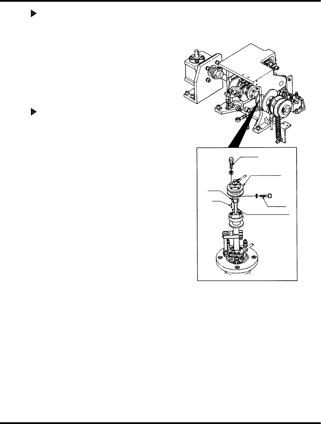
5.7 Insertion Head Insertion Pusher Perpendicularity/Height Check/Adjustment
SERVICE MANUAL
5.7−2
DA3SEC−83−8PO−A0
Adjusting perpendicularity
1. Loosen the bolt B and disengage the arm.
Then turn the shaft to measure the
perpendicularity.
(Adjust the perpendicularity within 0.1 mm.)
=CHECK=
As the bolt B is also fixed with cotter, tap
it lightly to release after loosening the
bolt.
(Be careful not to drop the arm after the
cotter released.)
Adjusting height
1. Disengage the bolt A (x 2).
2. Move the pusher rod up/down so that the gap
between it and the PC board (t = 1.6) may be
between 0 and 0.5 mm.
=CHECK=
When lifting the pusher rod, loosen the
bolt B to raise the pusher and then
retighten the bolt B. Check that the
perpendicularity does not change when
loosening the bolt B.
Bolt A
Bolt B
Cam follower
guide
Perpendicularity
Arm
Height
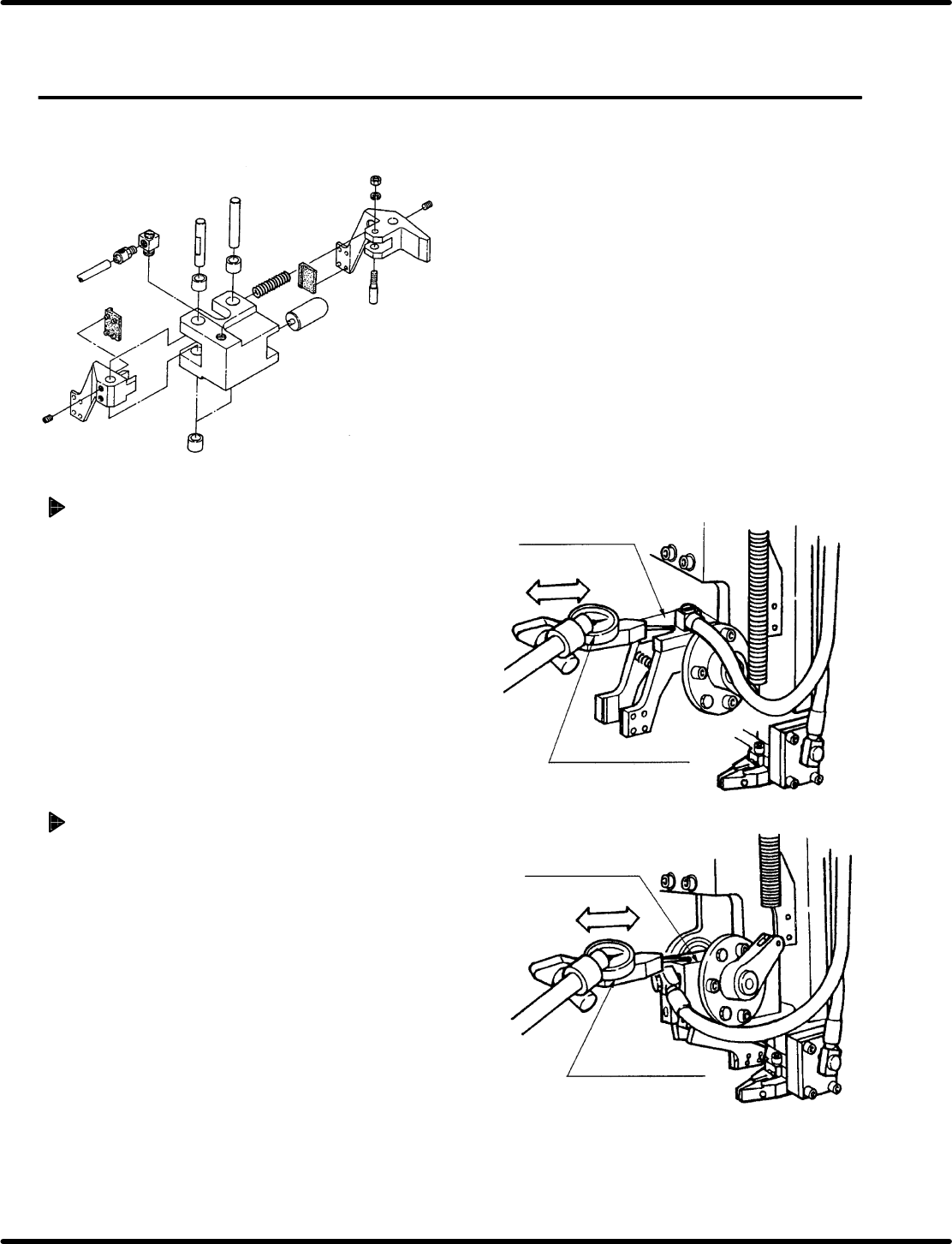
5.8 Insertion Head Insertion Chuck 90q Swing Check and Adjustment
SERVICE MANUAL
RH5
5.8−1
DA3SEC−83−8QO−A0
5.8 Insertion Head Insertion Chuck 90G Swing Check
and Adjustment
DA3SEC−83−8QO−A0
Sentence No.
When to perform
x When parts leads do not readily slip
into the guide chuck.
x When insertion errors occur
frequently.
x Allen wrench
x Box wrench
x Lever−operated dial gauge
Required tools
90G swing check (At parts handover)
1. T urn the hand wheel until the cam shaft is at the 0q
position on the digital sequence timer .
2. Attach the lever−operated dial gauge toe the guide
rail (fixed side ) on the X− Y table.
3. Set the measuring needle on the top surface of
the insertion chuck.
4. Move the X−Y table in the X direction by hand
checking insertion chuck parallelism against the
guide rail is within 0.05/15 − 20 mm.
210G swing check (During insertion)
1. T urn the hand wheel until the cam shaft is at the
210q position on the digital sequence timer.
2. Move the X−Y table in the X direction by hand
checking insertion chuck parallelism against the
guide rail is within 0.05/15 − 20 mm.
Lever−operated dial
gauge
X direction
The top of insertion
chuck
The rear of insertion
chuck
X direction
Lever−operated dial
gauge
Parallelism:
0.05/15 − 20 mm
Parallelism:
0.05/15 − 20 mm
RH5
5.8 Insertion Head Insertion Chuck 90q Swing Check and Adjustment
SERVICE MANUAL
5.8−2
DA3SEC−83−8QO−A0
Adjusting 90G swing (At parts
handover)
1. Loosen bolt A (x 2) on the transfer position
stopper (insertion chuck).
2. Turn the hand wheel and set the transfer position
stopper flush against the insertion chuck so that
the parallelism will be within 0.05/15−20 mm at
0q position on the digital sequence timer. Then
retighten bolts A (x 2) to secure the parts.
=CHECK=
Set the transfer position stopper flush against
the insertion chuck such that no gap results
between parts.
Adjusting 210G swing (During
insertion)
1. Loosen bolts B (x 2) on the insertion head lower
stopper.
2. Tighten the Y lock and turn the hand wheel ad
set the lower stopper flush against the insertion
chuck so that the parallelism will be within
0.05/15 − 20 mm at the 210q position on the
digital sequence timer. Then, retighten bolts A (x
2) to secure the parts.
=CHECK=
x Make sure the lower stopper is flush against the
insertion chuck.
x Do not position the lower stopper too close to
the rack. (Contacting parts will block the
insertion chuck from turning.)
3. After making adjustment, check 210q swing
again.
Transfer position
stopper
Insertion
chuck
Bolt A
Transfer
position
stopper
Lower
stopper
No gap
Bolt B
Insertion
chuck
A gap No gap
(NG) (OK)