Q170226E01.pdf - 第161页
RH5 5.18 Anvil Cutter Blade Replacement and Adjustment SERVICE MANUAL 5.18−2 DA3SEC−83−9AO−A0 Moving blade A replacement 1. Remove bolt A (x 4) fixing moving blades A in place. 2. Set new blades so that the distance from…
5.18 Anvil Cutter Blade Replacement and Adjustment
SERVICE MANUAL
RH5
5.18−1
DA3SEC−83−9AO−A0
5.18 Anvil Cutter Blade Replacement and Adjustment
DA3SEC−83−9AO−A0
Sentence No.
When to perform
x When parts leads are not cut.
x When part leads are bent after being cut.
x When insertion errors occur frequently.
x Allen wrench
x Gap gauge
Required tools
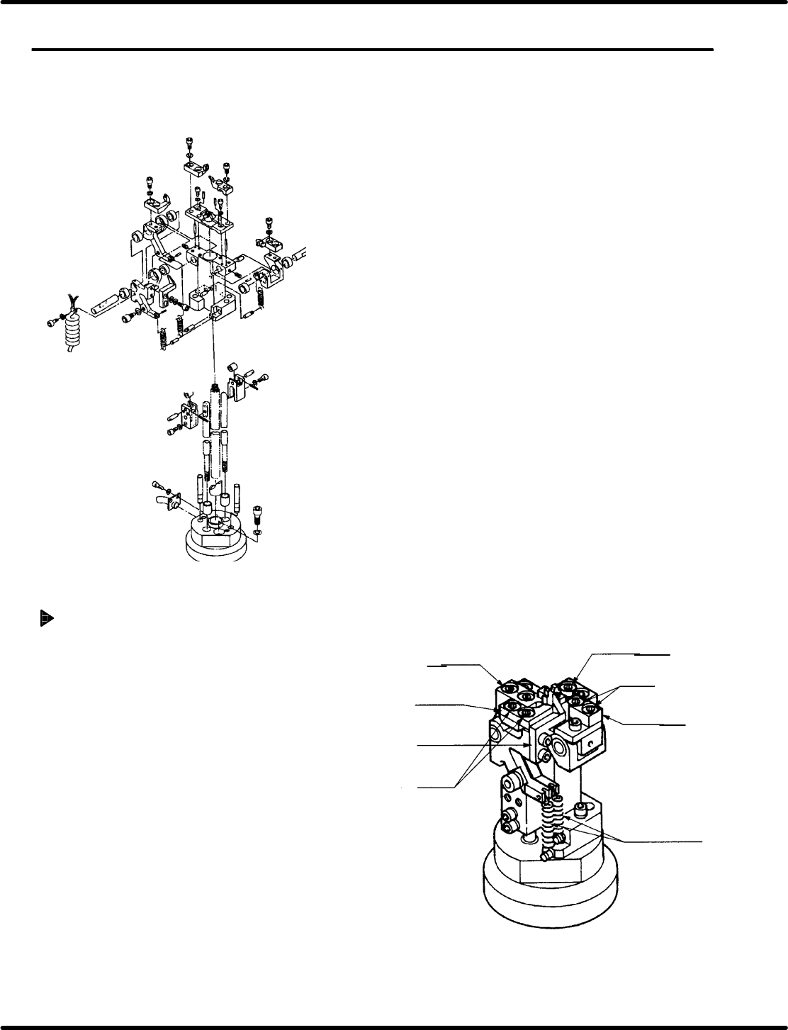
Fixed blade replacement
1. Remove bolt A (x 4) securing the fixed blades in
place.
2. Insert new blades being careful to install them
in the proper places, and fix them in place with
bolt A (x 4).
=REFERENCE=
There are two types of fixed blades.
Be sure to install the blades in the proper
places.
Moving blade A
Bolt A
Fixed blade
Spring for cut
& clinch lever
Fixed blade
Moving
blade A
Moving
blade B
Bolt A
RH5
5.18 Anvil Cutter Blade Replacement and Adjustment
SERVICE MANUAL
5.18−2
DA3SEC−83−9AO−A0
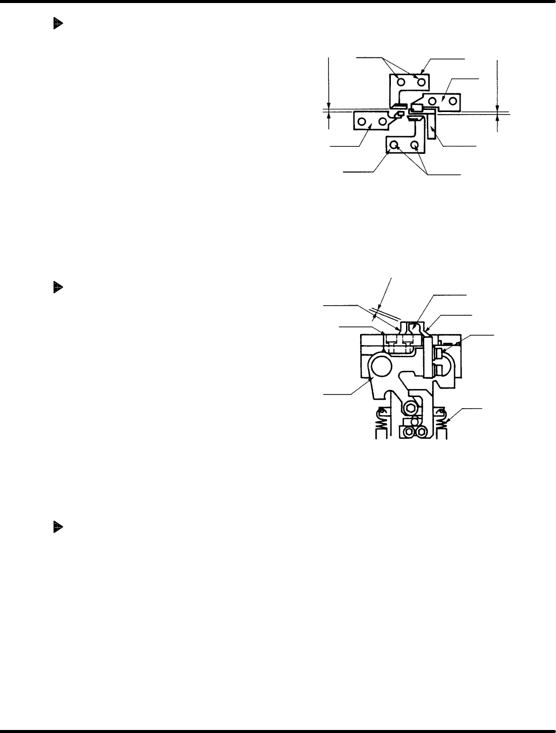
Moving blade A replacement
1. Remove bolt A (x 4) fixing moving blades A
in place.
2. Set new blades so that the distance from
the fixed blade is between 0.05 and 0.1 mm.
Then, fix them in place with bolt A (x 4).
=REFERENCE=
x Before attaching a new blade remove
the old blade and demagnetize the
body.
x Before determining blade meshing,
remove the spring for the cut and clinch
lever.
x Make size measurements using a gap
gauge.
Moving blade B replacement
1. Remove bolt B (x 2) fixing moving blades B
in place.
2. Set new blades so that the distance from
the fixed blade is between 0.05 and 0.1 mm.
Then, fix them in place with bolt B (x 2).
=REFERENCE=
x Before attaching a new blade, remove
the old blade and demagnetize the
body.
x Before determining blade meshing,
remove the spring for the cut and clinch
lever.
x Make size measurements using a gap
gauge.
Cutting check
1. After replacing the cutter blades, check
each blade for cutting using a I 0.3 steel
wire.
Bolt A
Moving
blade A
Moving
blade B
Moving
blade A
Fixed
blade
Fixed
blade A
Bolt A
0.05 − 0.1 mm
0.05 − 0.1 mm
Moving
blade A
Moving
blade B
Moving
blade A
Fixed
blade A
Bolt B
Spring
Lever
0.05 − 0.1 mm
5.19 Anvil Parallelism Check and Adjustment
SERVICE MANUAL
RH5
5.19−1
DA3SEC−83−9BO−A0
5.19 Anvil Parallelism Check and Adjustment
DA3SEC−83−9BO−A0
Sentence No.
When to perform
x When the guide pin gets caught on the insertion
hole.
x When leads are clinched or bent unevenly.
x Lever−operated dial gauge
x Allen wrench
Required tools
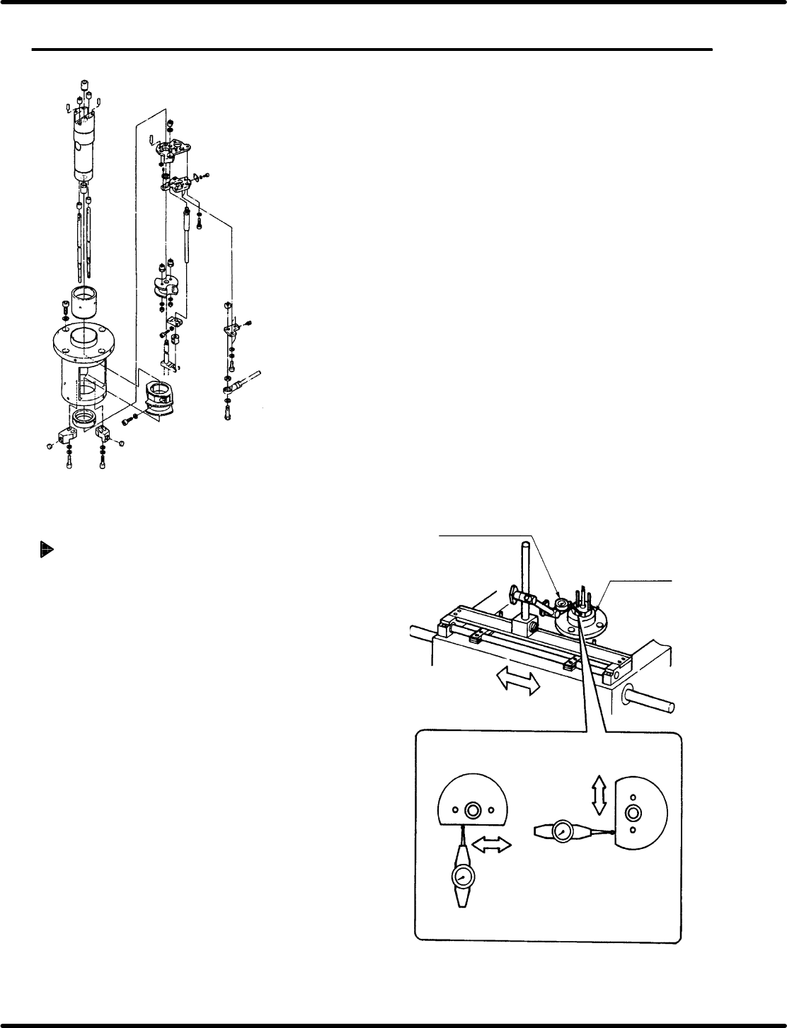
Measuring parallelism (During
insertion in the X direction)
1. T urn the hand wheel until the cam shaft is
approximately at the 210q position on the digital
sequence timer .
2. Attach the lever−operated dial gauge to the guide
rail (fixed side) on the X−Y table. Set the
measuring needle on the side surface (flat
surface) of the anvil dust cover .
3. Move the X−Y table in the X direction by hand and
check the parallelism is between 0.05/25−30 mm.
=REFERENCE=
If sliding the X− Y table by hand, make sure
the table does not slip in the Y direction.
Lever−operated dial
gauge
Dust cover
(Insertion in the
Y direction)
(Insertion in the
X direction)
Parallelism:
0.05/25 − 30 mm