Q170226E01.pdf - 第321页
RH5 8.3 List of Jumper Switch Settings SERVICE MANUAL 8.3−24 DA3SEC−85−540−B0 The following registers are interchangeable with the 8251A: Receive data buffer register , Send buffer data register , Status register and Mod…
8.3 List of Jumper Switch Settings
SERVICE MANUAL
RH5
8.3−23
DA3SEC−85−540−B0
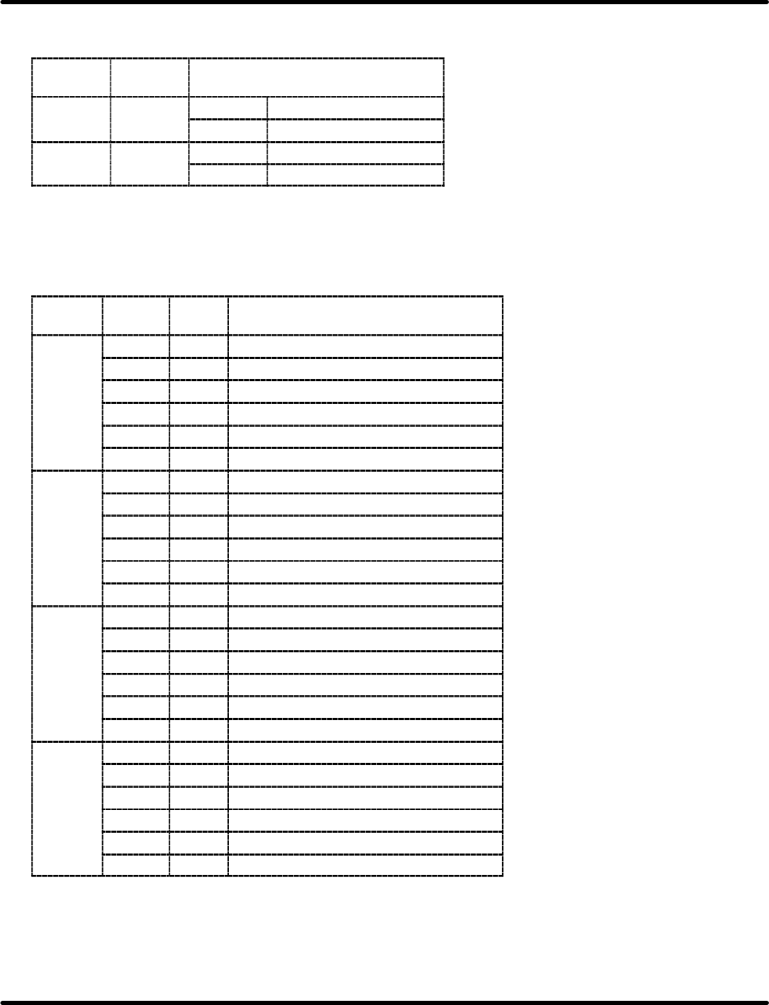
(5) Jumper setting
Input jumpers for WD37C65 mode setting are as follows:
Jumper
Signal
name
Content
1of
JP12
DR
V
SHORT 0 16 MHZ
JP12
DR
V
OPEN 1 9.6 MHz
2of
JP12
PCV
AL
SHORT 0 187 nsec
JP12
PCV
AL
OPEN 1 125 nsec
Serial interface MB89371
This board is equipped with four serial I/O interface channels. They are controlled by the two SDTRs
(Serial data transmitter receiver MB89371).
The four channels are TTY, HOST, SIO1 and SIO2. The relationship between each I/O port address and
register is given below.
Used
device
I/O
address
R/W Register
30 R Receive data buffer register
30 W Send data buffer register
TTY
32 R Status register
TTY
32 W Mode/command register
34 W Baud rate setting register
36 W Mode setting register
38 R Receive data buffer register
38 W Send data buffer register
HOST
3A R Status register
HOST
3A W Mode/command register
3C W Baud rate setting register
3E W Mode setting register
50 R Receive data buffer register
50 W Send data buffer register
SIO1
52 R Status register
SIO1
52 W Mode/command register
54 W Baud rate setting register
56 W Mode setting register
58 R Receive data buffer register
58 W Send data buffer register
SIO2
5A R Status register
SIO2
5A W Mode/command register
5C W Baud rate setting register
5E W Mode setting register
RH5
8.3 List of Jumper Switch Settings
SERVICE MANUAL
8.3−24
DA3SEC−85−540−B0
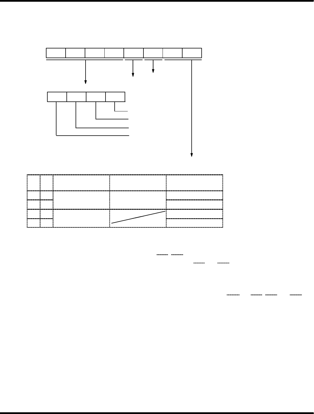
The following registers are interchangeable with the 8251A: Receive data buffer register, Send buffer
data register, Status register and Mode/command register. The mode setting register is set conforming to
the specification after resetting. Bit configuration is given below. After resetting, FO
H
is set being
interchangeable with the 8251A.
Modem control
function
Loop−back
self−check
TRNEMP mask
TRNRDY mask
RCVRDY mask
SYNDET mask
Interrupt mask bit
Clock switching
0: Mask ON (Interrupt disabled)
1: Mask OFF (Interrupt enabled)
“1” is set after resetting.
B7 B6 B5 B4 B3 B2 B1 B0
B7
B6
B5 B4
B1 B0
TRNCLK & RVCLK
of inside SDTR
TRNCLK & RVCLK
of MB89371
TRNEMP, ST1
0 0 Sent from external
lk
Input
TRNEMP
0 1
clock
I
npu
t
ST1
1 0 Uses internal baud
t
t
TRNEMP
1 1
rate generator.
ST1
=REFERENCE=
Modem control function
x Set the level of the modern control line CTS
, DSR by setting either “0” or “1” at B2.
x When “1” is set for B2, the “L” level is set at terminals CTS
and DSR.
x When set to “0” for B2, the normal operation mode is set.
=REFERENCE=
Loop−back self−check
x In the loop−back self−check mode, terminals TRNDT and RCVDT, RTS
and CTS, DTR and DSR
are connected each other inside the MB89371. Transmission, reception and checks are performed
entirely by the MB89371.
Set 1 at B3 to engage this mode.
Set 0 at B3 to engage normal operation mode.
8.3 List of Jumper Switch Settings
SERVICE MANUAL
RH5
8.3−25
DA3SEC−85−540−B0
The baud rate setting register sets the desired baud rate both when using the internal clock and using the
ST1 output.
Standard clock setting is 2.4576 MHz. Bit configuration is given below.
Counter reset
Baud rate setting
0: Normal operation
1: Counter reset
B7 B6 B5 B4 B3 B2 B1 B0
0
0
0
Relationship between register setting and baud rate
Baud rate setting register f
RVC
Baud rate (bps)
B3 B2 B1 B0 f
RVC
1/1 mode 1/16 mode 1/64 mode
0 0 0 0 1.2288 MHz
0 0 0 1 614.4 kHz 38400 9600
0 0 1 0 307.2 kHz 19200 4800
0 0 1 1 153.6 kHz 153600 9600 2400
0 1 0 0 76.8 kHz 76800 4800 1200
0 1 0 1 38.4 kHz 38400 2400 600
0 1 1 0 19.2 kHz 19200 1200 300
0 1 1 1 9600 Hz 9600 600 150
1 0 0 0 4800 Hz 4800 300 75
1 0 0 1 2400 Hz 2400 150
1 0 1 0 1200 Hz 1200 75
1 0 1 1 600 Hz 600
1 1 0 0 300 Hz 300
1 1 0 1 150 Hz 150
1 1 1 0 75 Hz 75
=REFERENCE=
Crossed out blocks can’t be used because they don’t satisfy requirements between f
RVC,
f
TRN
and
f
CLK.