Q170226E01.pdf - 第198页
5.32 Setting Offset V alues SERVICE MANUAL RH5 5.32−3 DA3SEC−83−9Q0−A0 Initial setting of individual machine data 1. Enter 0 in origin offset and camera offset for individual machine setting screen. x Press ESC. x Press …
RH5
5.32 Setting Offset Values
SERVICE MANUAL
5.32−2
DA3SEC−83−9Q0−A0
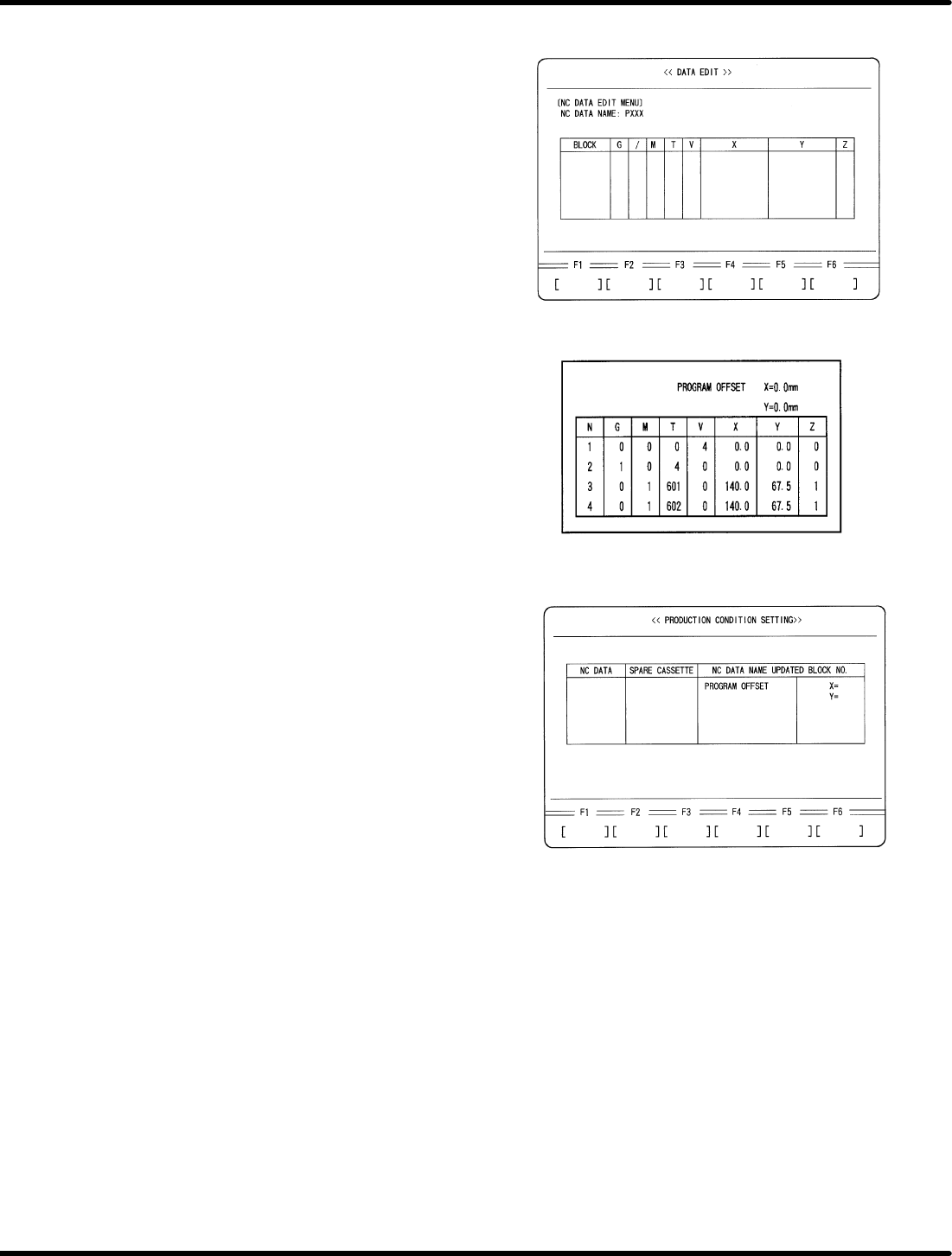
3. Enter an NC data name.
x Enter a name of NC data to be created
for recognition adjustment.
x Press ENTER.
x Press F1 (YES).
4. Create an NC data for recognition
adjustment.
x Enter data as follows.
5. Enter program offset.
x Press ESC three times.
x Press F1 (PRODUCTION CONDITION
SETTING).
x Select the NC data for recognition
adjustment with npkeys.
x Using mokeys, move the cursor to
PROGRAM OFFSET and enter as
follows:
X = −160.0 mm
Y = −255.0 mm
5.32 Setting Offset Values
SERVICE MANUAL
RH5
5.32−3
DA3SEC−83−9Q0−A0
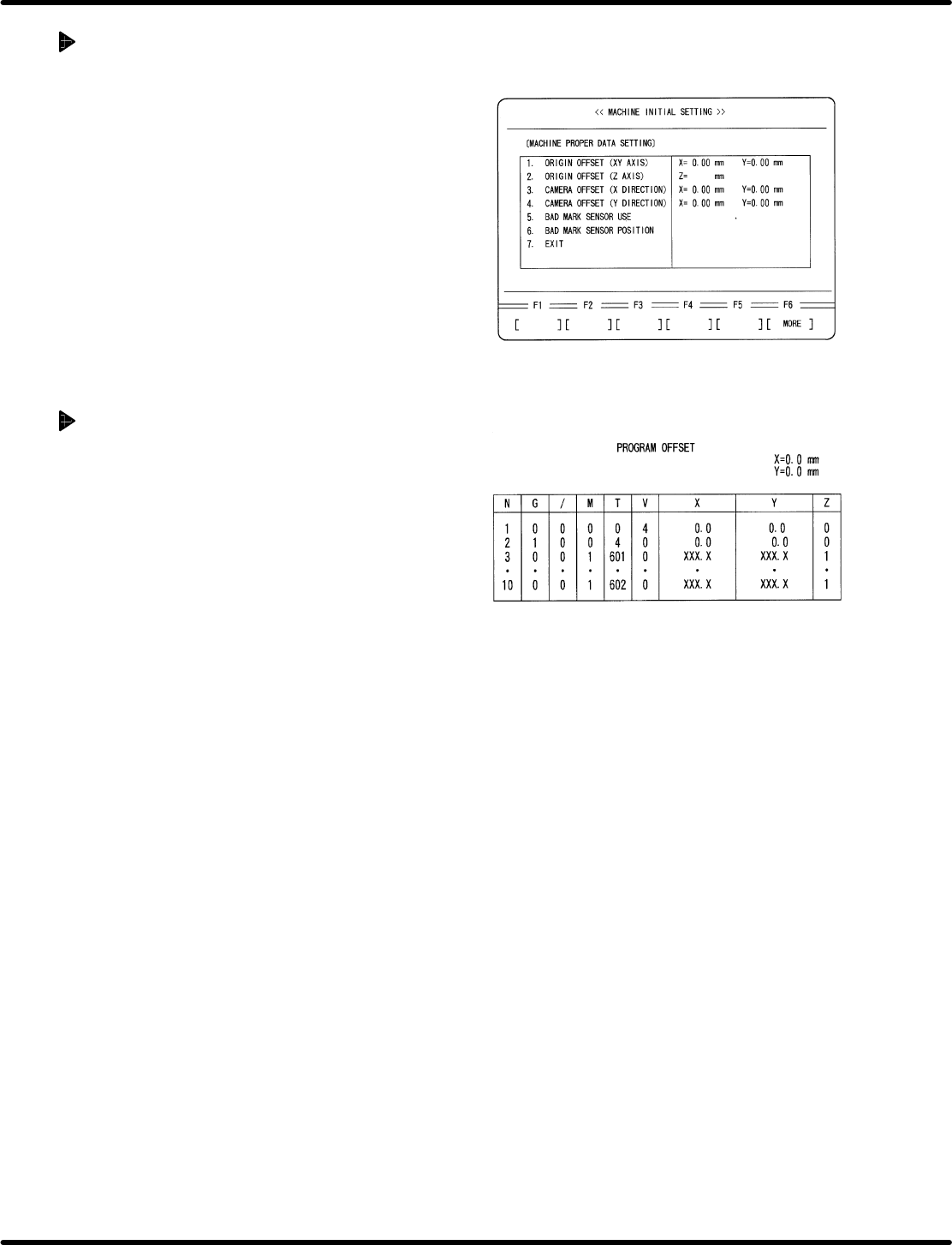
Initial setting of individual
machine data
1. Enter 0 in origin offset and camera offset for
individual machine setting screen.
x Press ESC.
x Press F6. (MORE)
x Press F1 (MACHINE INITIAL SETTING)
x Press F2 (INDIVIDUAL MACHINE DATA)
x Enter 0 in ORIGIN OFFSET (X, Y) and
CAMERA OFFSET (X, Y).
=REFERENCE=
Customer’s production board can also
be used for adjustment if origin board is
unavailable.
When using a customer’s board
1. Select two insertion directions X and Y for
the board and create an NC data that allows
only the selected two points to be operated.
=REFERENCE=
Select two X and Y positions near the
center of the PC board.
=CHECK=
Enter /7 (unconditional skip) in the
unnecessary blocks or copy an editing
NC data and delete unnecessary part of
the data.
2. Perform teaching with the NC data created
in step 1 and create data so that the guide
pin may be aligned with the center of the
board hole, regarding both X and Y direction
data.
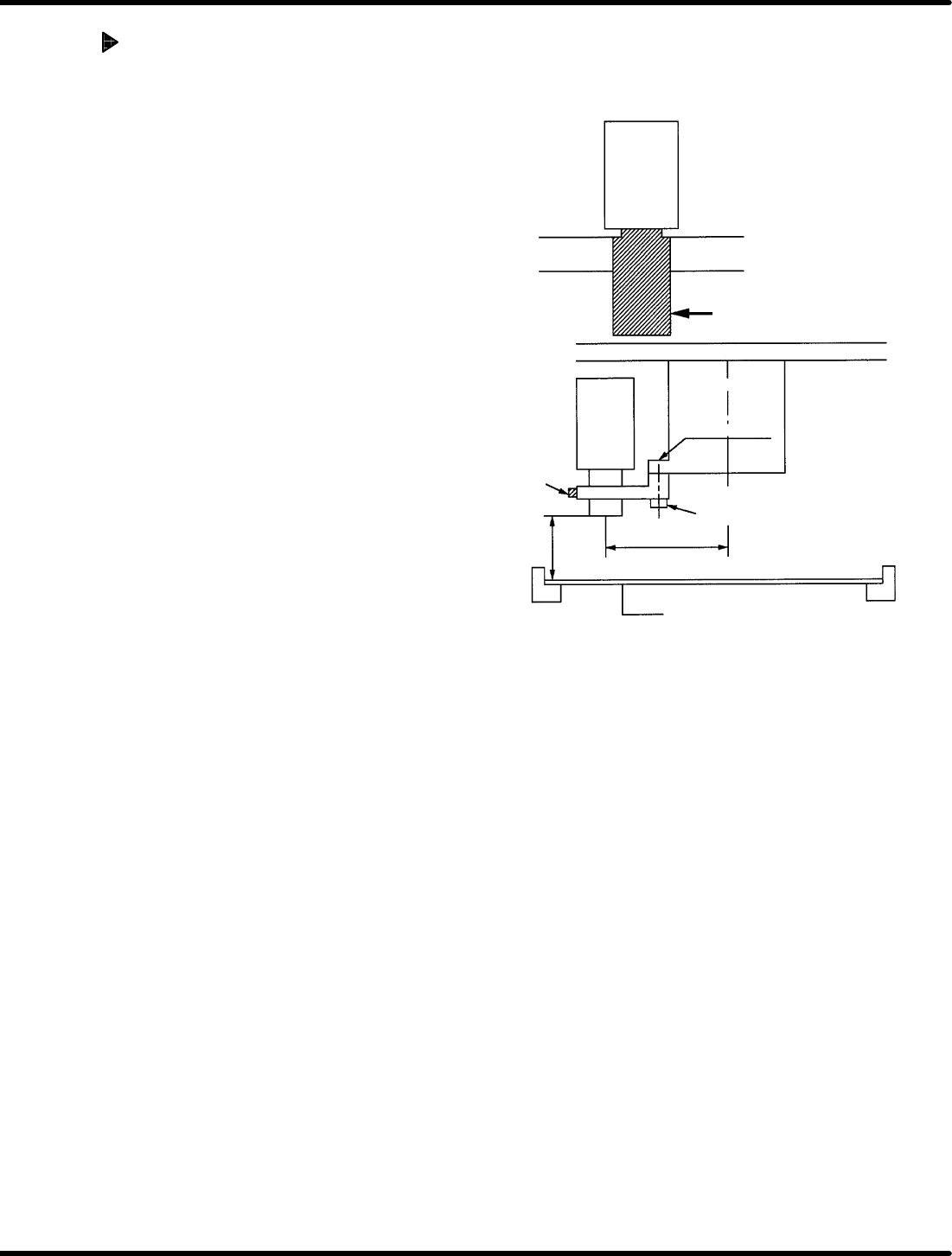
Attach the brackets as
shown in the figure.
Bracket Bracket
Camera lens
Camera
Insertion head
Head flange
Bolt (1)
Bolt (2)
90.0 mm
Bracket (1)
150 H
1mm
PC board
(thickness t = 1.6 mm)
RH5
5.32 Setting Offset Values
SERVICE MANUAL
5.32−4
DA3SEC−83−9Q0−A0
Camera installation
1. Attach bracket (1) to the head flange and
secure with bolt (1).
2. Install camera to the bracket (1).
=REFERENCE=
Camera height
x 148.4 mm from the board top (When
board thickness is 1.6 mm)
x 150.0 mm from the bottom of board
(lower side of rail)
Camera installation direction
x Install the camera so that the model
number label can be seen from the
front side.
x Recognition camera setting
(Teli camera only)
=CHECK=
x As for NEC camera, recognition
camera setting will not be
performed.