Q170226E01.pdf - 第223页
(OK) (NG) (NG) RH5 5.36 Y Lo ck Cy linder Replacement and Adjustment SERVICE MANUAL 5.36−2 DA3SEC−83−9U0−A0 10. Press “Y INSERT” on the sub−control panel. 11 . Turn the hand wheel one turn to set the insertion head and a…
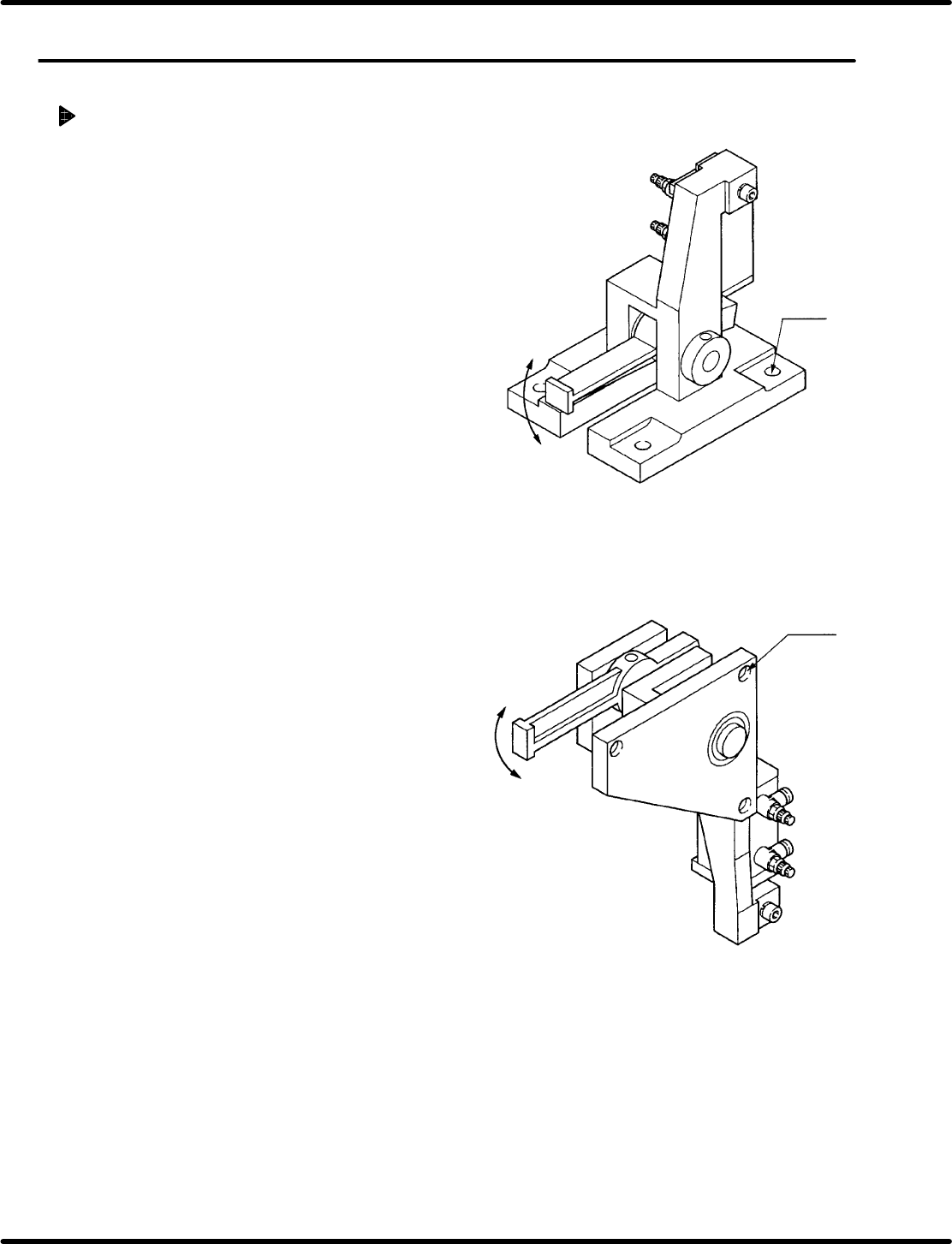
(4−M8)
(3−M8)
(Insertion head swivel lock cylinder)
(Anvil swivel lock cylinder)
5.36 Y Lock Cylinder Replacement and Adjustment
SERVICE MANUAL
RH5
5.36−1
DA3SEC−83−9U0−A0
5.36 Y Lock Cylinder Replacement and Adjustment
DA3SEC−83−9U0−A0
Sentence No.
Replacing/adjusting Y lock cylinder
1. Turn the hand wheel to set the digital
sequence timer to 100q.
2. Cut off the power to the machine and air
supply.
3. Remove the bolt attaching Y lock cylinder.
(Insertion head: 4−M8, Anvil: 3−M8)
4. Disconnect air piping and remove the lead
switch.
=CHECK=
Mark the air piping and lead switch
before removing.
5. Detach the old cylinder.
=REFERENCE=
The cylinder can be detached by removing
the bolt (2−M4) and disengaging the rod
end nut.
6. Assemble a new cylinder and apply grease
to the fulcrum pin, etc.
=CHECK=
Be careful not to tighten the bolt (2−M4)
extremely. Too tightened bolt may
impair the movement of the cylinder.
(The cylinder must move smoothly by
hand.)
7. Install the lead switch and air piping in the
original state.
=CHECK=
Surely install the lead switch and air
piping in its original position.
8. Lock the fitting bolt of the Y lock cylinder
temporarily.
(Insertion head: 4−M8, Anvil: 3−M8)
9. Supply air and turn ON power to the
machine.
(OK)
(NG)
(NG)
RH5
5.36 Y Lock Cylinder Replacement and Adjustment
SERVICE MANUAL
5.36−2
DA3SEC−83−9U0−A0
10. Press “Y INSERT” on the sub−control panel.
11. Turn the hand wheel one turn to set the
insertion head and anvil in Y direction−facing.
=REFERENCE=
T urn the handle by 90q for insertion head
cylinder, and by 80q for anvil cylinder .
12. Secure the Y lock cylinder without making a
gap between the notch at the end of the lever
and cam follower at the end of the swivel
lever.
=CHECK=
When securing the anvil Y lock cylinder,
lift the unit completely to upward and
secure it without making a gap between
the notch and the cam follower at the
end of the swivel lever.
=CHECK=
Make sure that the notch is positioned at
the center of the cam follower.
If off−center, disengage the rod end nut
of the cylinder and adjust the cylinder
stroke.
13. Return the hand wheel to its origin and
remove it.
14. Press “SEMI” and “1BLOCK” on the main
control panel.
15. Press “CONTROL PANEL ENABLE” and
“CAM ROTATION ENABLE” on the
sub−control panel.
16. Hold down the “CAM ROTATION” switch and
turn ON and OFF “Y INSERT” switch to make
sure the Y lock unit moves smoothly.
17. Press “Y INSERT” and “CAM ROTATE” on
the sub−control panel to rotate both the head
and the anvil in Y direction.
18. Cut off the power to the machine and air
supply.
19. When cutting off the air supply, make sure
both the head and the anvil do not swivel in X
direction.

5.36 Y Lock Cylinder Replacement and Adjustment
SERVICE MANUAL
RH5
5.36−3
DA3SEC−83−9U0−A0
=CHECK=
When the head or the anvil swivels in X
direction in cutting the air off, retry the
above procedure (from 9 to 16).
=CHECK=
Replacement of the Y lock cylinder is
hazardous. Before replacing it, make
sure the digital sequence timer is set to
100q.