Q170226E01.pdf - 第249页
RH5 7.1 NC Unit Adjustment SERVICE MANUAL 7.1−2 DA3SEC−84−290−A0 7.1.2 AC Servomotor Drivers Adjustment (1) Enter the parameter setting values of motor drivers and CNC board. (2) Perform origin return. Then, while checki…
7.1 NC Unit Adjustment
SERVICE MANUAL
RH5
7.1−1
DA3SEC−84−290−A0
7.1 NC Unit Adjustment
DA3SEC−84−290−A0
Sentence No.
7.1.1 Table Signal Connection Check
(1) + LM and − LM switch check
In this state, move the X−axis in the + direction, checking the X + limit monitor lights up. Next, move
the X−axis in the − direction, checking the X − limit monitor lights up. Check both the Y and Z axes in
the same way.
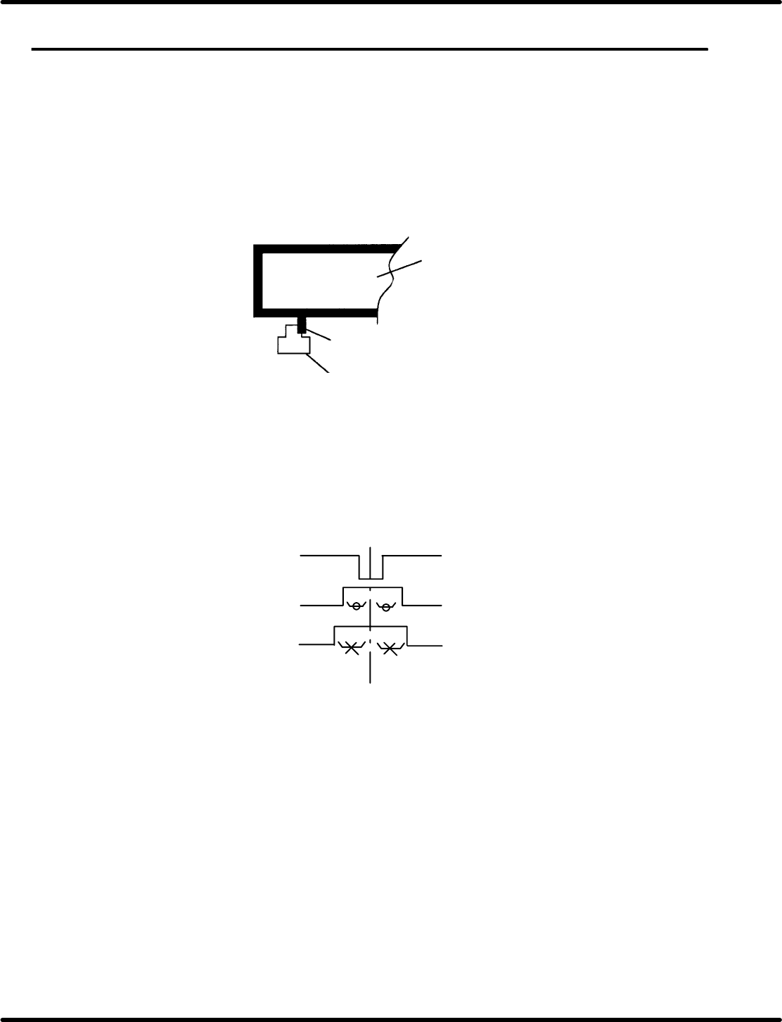
(2) + LM and − LM switch installation position check
Slowly push the table in the direction of the limit switch. Stop pushing the table on the instant the limit
sensor detects the table.
X−Y table
Slit plate
Limit sensor photohimic
Figure 7.1−1−: + LM and − LM Installation Position
(3) Origin slow signal and table origin signal
Adjust the origin slow signal and table origin signal on the center of the Z phase signal generated by
the pulse encoder.
Z phase signal
Table origin signal
Origin slow signal
Center on Z phase signal
Center on Z phase signal
Figure 7.1−2−
(4) Safety SW check
Safety switches (limits switches ) are installed on the X/Y axis’ center and on both sides of the Z axis.
They trip when the table runs out of control.
Check each safety switch trips when doused (the servolock engages). If the safety switch (limit
switch) is turned ON (doused) while the table is moving (safety limit error stop), speed command
voltage inside the AC motor driver is cut to 0 V (zero−clamp), forcing the table to stop instantly.
RH5
7.1 NC Unit Adjustment
SERVICE MANUAL
7.1−2
DA3SEC−84−290−A0
7.1.2 AC Servomotor Drivers Adjustment
(1) Enter the parameter setting values of motor drivers and CNC board.
(2) Perform origin return. Then, while checking the current position in JOG mode, adjust the driver offset
(Cn−00−0003−b***) so that the current position value stops at 0.00.
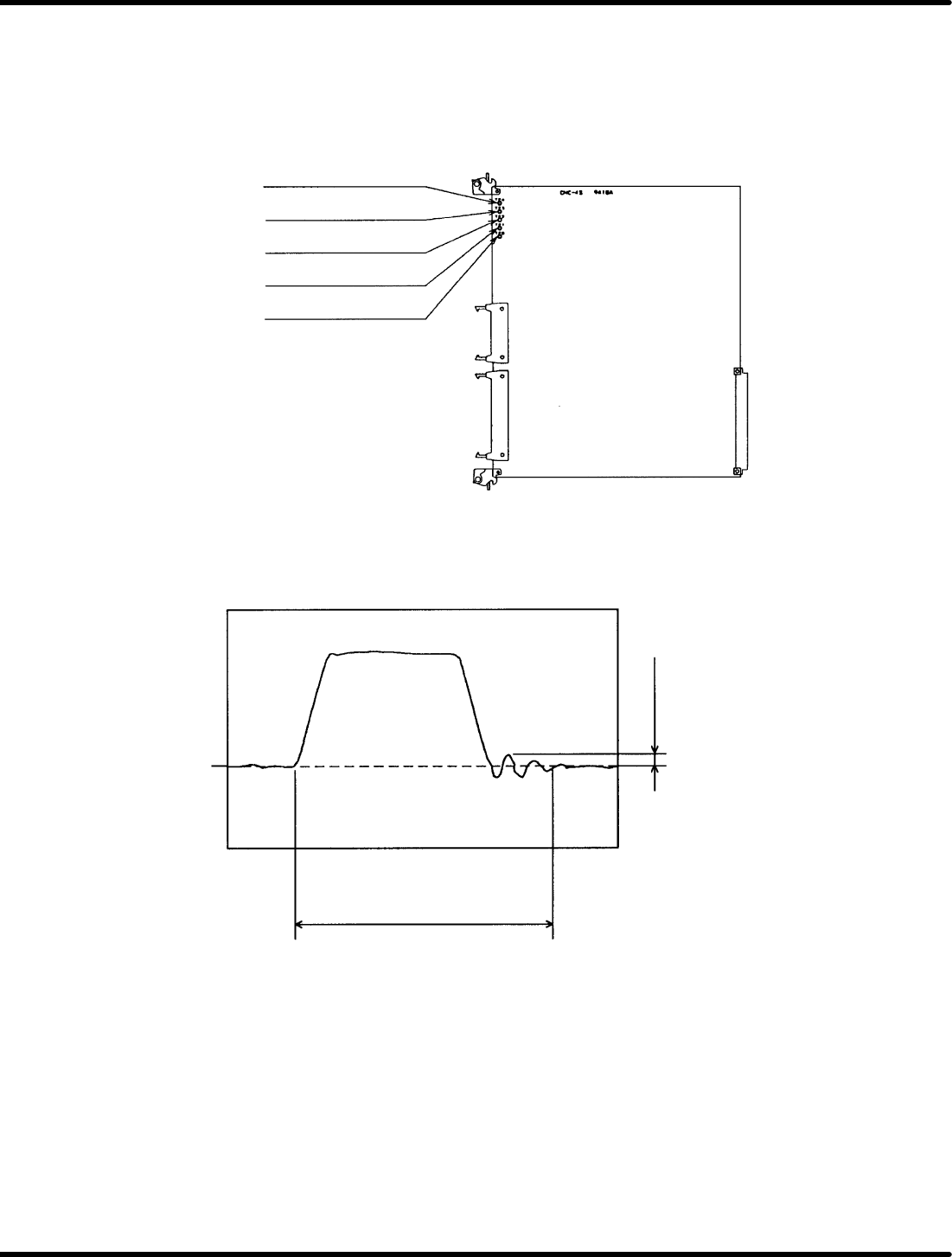
(3) Connect the CNC board’s speed monitor (VTG−M)to an oscilloscope.
TP4: Camshaft speed
monitor
TP3: Z−axis speed monitor
TP2: Y−axis speed monitor
TP1: X−axis speed monitor
TPG: GND
Figure 7.1−3− CNC−4S Board Check Pin Assignments
(4) Measure the waveform of the speed monitor (VTG−M) and make sure there is no hunting overshoot,
undershoot nor rounding in the waveform.
Cam: No particular restriction
Z: 190mS or less when moving
two cassettes
XY: 130mS or less when moving
55 mm.
100mV or less
0V
Figure 7.1−4− Speed Monitor Waveform

7.1 NC Unit Adjustment
SERVICE MANUAL
RH5
7.1−3
DA3SEC−84−290−A0
If the motor oscillates
1. Increase/decrease the torque command filter constant (Cn−17) in 1 increment until the oscillation is
eliminated.
2. If the oscillation persists even after the adjustment of 1) above, decrease the speed loop gain (Cn−04)
in 5 increments to eliminate the problem. At this time, measure the waveform of the speed monitor
(VTG−M) to make sure no hunting, overshoot undershoot, nor rounding in the waveform is found.
If hunting, overshoot, undershoot or rounding in the waveform exists
1. Increase the speed loop gain (Cn−04) in 5 increments to remedy the problem.
At this time, measure the waveform of the speed monitor (VTG−M) to make sure no hunting overshoot,
undershoot, nor rounding in the waveform is found.