Q170226E01.pdf - 第299页
RH5 8.3 List of Jumper Switch Settings SERVICE MANUAL 8.3−2 DA3SEC−85−540−B0 Command voltage full scale changeover jumper post − JP5 to 8 Set the output voltage at r 10V . Short circuit condition Output 123 2−3 shot r 10…
8.3 List of Jumper Switch Settings
SERVICE MANUAL
RH5
8.3−1
DA3SEC−85−540−B0
8.3 List of Jumper Switch Settings
DA3SEC−85−540−B0
Sentence No.
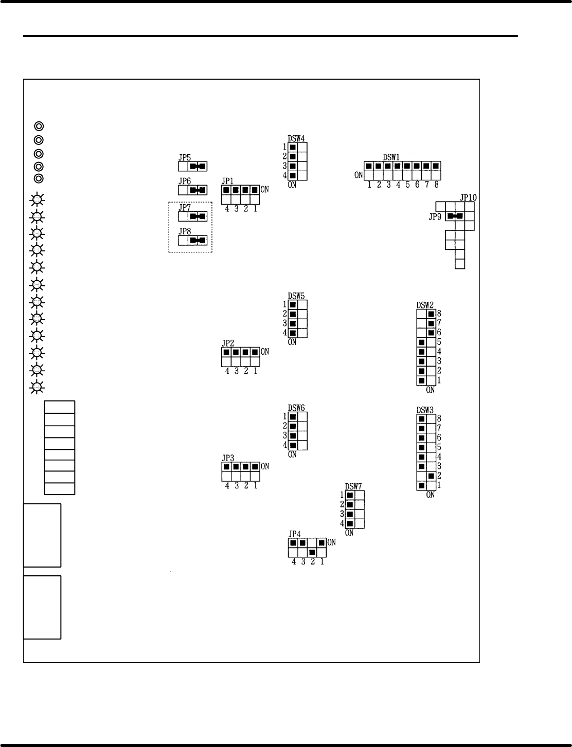
8.3.1 CNC−4S (I) Board Setting
CNC−4S (I)
TP4 4−axis voltage terminal
TP3 3−axis voltage terminal
TP2 2−axis voltage terminal
TP1 1−axis voltage terminal
TPG Ground terminal
LED 12 4−axis origin
LED 11 3−axis origin
LED 10 2−axis origin
LED 9 1−axis origin
LED 8 4−axis in operating
LED 7 3−axis in operating
LED 6 2−axis in operating
LED 5 1−axis in operating
LED 4 Master general purpose LED
LED 3 Master general purpose LED
LED 2 Master general purpose LED
LED 1 Master general purpose LED
VRB4
VRB3
VRB2
VRA1
VRA2
VRA3
VRA4
VRB1
4−axis offset
3−axis offset
2−axis offset
1−axis offset
4−axis gain
3−axis gain
2−axis gain
1−axis gain
CN2
CN1
RH5
8.3 List of Jumper Switch Settings
SERVICE MANUAL
8.3−2
DA3SEC−85−540−B0
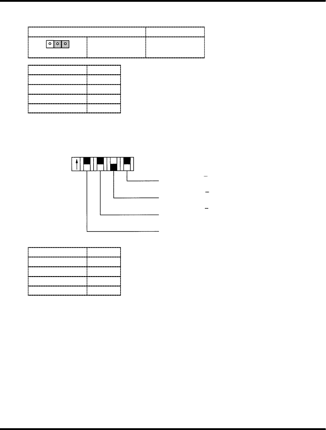
Command voltage full scale changeover jumper post − JP5 to 8
Set the output voltage at r10V.
Short circuit condition
Output
123
2−3 shot r10V
Jumper switch Axis
JP5 1st axis
JP6 2nd axis
JP7 3rd axis
JP8 4th axis
Encoder input logic select switch − JP1 to 4
Allows encoder input logic of phases A, B and Z to be selected.
Phase A
Phase B
Phase Z
General−purpose
input switch
OFF: A
ON: A
OFF: B
ON: B
OFF: Z
ON: Z
ON
OFF
JP4321
Jumper switch Axis
JP1 1st axis
JP2 2nd axis
JP3 3rd axis
JP4 4th axis
8.3 List of Jumper Switch Settings
SERVICE MANUAL
RH5
8.3−3
DA3SEC−85−540−B0
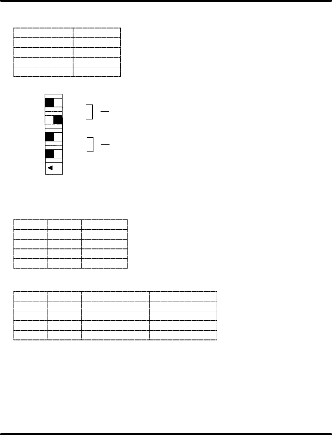
Output pulse CW/CCW function and multiplication changeover switch −
DSW4 to 7
DIP switch Axis
DSW4 1st axis
DSW5 2nd axis
DSW6 3rd axis
DSW7 4th axis
Multiplication
changeover
CW/CCW function
changeover
S0
S1
S2
S3
1
2
3
4
ON OFF
DSW
(1) Multiplication changeover
S2
S3 Multiplication
ON ON x1
ON OFF x2
OFF ON x4
OFF OFF Inhibited
(2) CW/CCW changeover
S0
S1 CW signal CCW signal
ON ON CW positive logic CCW positive logic
OFF ON POUT positive logic PDIR positive logic
ON OFF CW negative logic CCW negative logic
OFF OFF POUT negative logic PDIR negative logic