Q170226E01.pdf - 第250页
7.1 NC Unit Adjustment SERVICE MANUAL RH5 7.1−3 DA3SEC−84−290−A0 If the motor oscillates 1. Increase/decrease the torque command filter constant (Cn−17) in 1 increment until the oscillation is eliminated. 2. If the oscil…
RH5
7.1 NC Unit Adjustment
SERVICE MANUAL
7.1−2
DA3SEC−84−290−A0
7.1.2 AC Servomotor Drivers Adjustment
(1) Enter the parameter setting values of motor drivers and CNC board.
(2) Perform origin return. Then, while checking the current position in JOG mode, adjust the driver offset
(Cn−00−0003−b***) so that the current position value stops at 0.00.
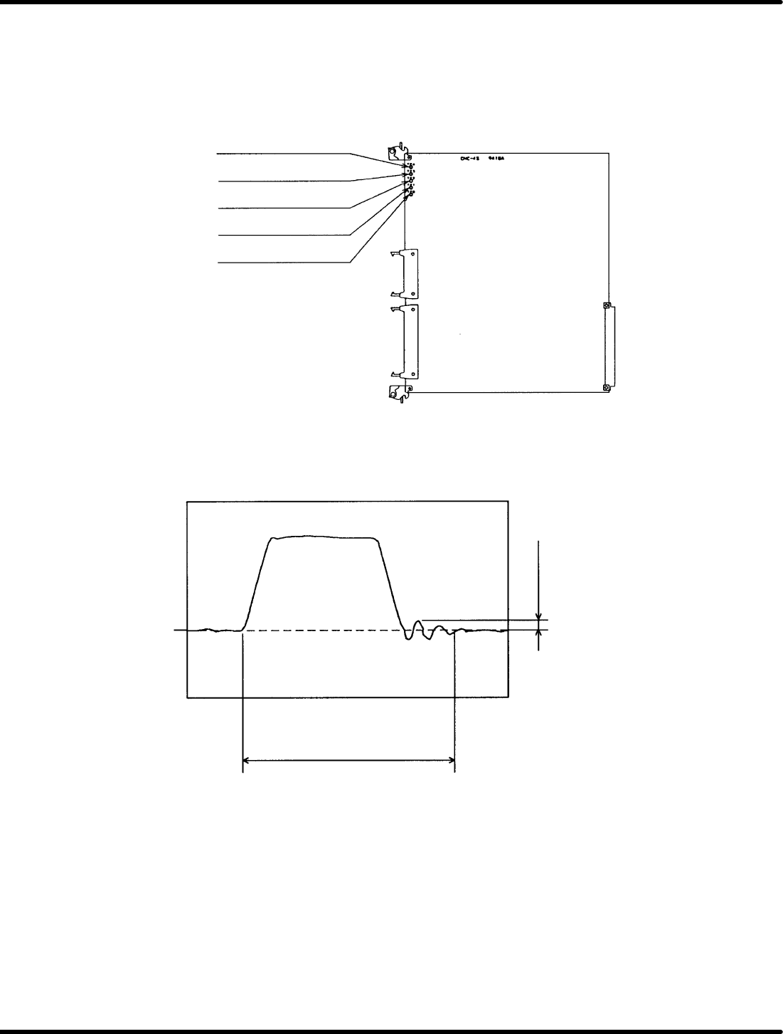
(3) Connect the CNC board’s speed monitor (VTG−M)to an oscilloscope.
TP4: Camshaft speed
monitor
TP3: Z−axis speed monitor
TP2: Y−axis speed monitor
TP1: X−axis speed monitor
TPG: GND
Figure 7.1−3− CNC−4S Board Check Pin Assignments
(4) Measure the waveform of the speed monitor (VTG−M) and make sure there is no hunting overshoot,
undershoot nor rounding in the waveform.
Cam: No particular restriction
Z: 190mS or less when moving
two cassettes
XY: 130mS or less when moving
55 mm.
100mV or less
0V
Figure 7.1−4− Speed Monitor Waveform

7.1 NC Unit Adjustment
SERVICE MANUAL
RH5
7.1−3
DA3SEC−84−290−A0
If the motor oscillates
1. Increase/decrease the torque command filter constant (Cn−17) in 1 increment until the oscillation is
eliminated.
2. If the oscillation persists even after the adjustment of 1) above, decrease the speed loop gain (Cn−04)
in 5 increments to eliminate the problem. At this time, measure the waveform of the speed monitor
(VTG−M) to make sure no hunting, overshoot undershoot, nor rounding in the waveform is found.
If hunting, overshoot, undershoot or rounding in the waveform exists
1. Increase the speed loop gain (Cn−04) in 5 increments to remedy the problem.
At this time, measure the waveform of the speed monitor (VTG−M) to make sure no hunting overshoot,
undershoot, nor rounding in the waveform is found.

RH5
7.1 NC Unit Adjustment
SERVICE MANUAL
7.1−4
DA3SEC−84−290−A0
7.1.3 AC Motor Power ON
(1) Turn On power but make sure the safety switches stay OFF.
=CHECK=
In this state, keep hands on the EMERGENCY STOP at all times . If the X−Y or Z tables start to
move, shut OFF power immediately.
(2) Check each table is locked into position (servolock).
This position is stored in the NC unit. If the table is some how moved, it will return to its original
position immediately.
=CHECK=
In this state, try moving the table. If it is too weak to return in position, or if the motor turns but the
table does not move, gradually raise the speed loop gain (Cn−04) of the motor drier, within the 1 to
5 range.
If the table overly shakes while returning in position gradually lower the speed loop gain (C4−04)
mentioned above, within the 1 to 5 range.
If this proves ineffective, check wiring, the AC motor driver and CNC board.
(3) Interlock activation check
Turn the safety switches (limit switches) on the X, Y and Z axes. (Only while the sensors are on,
“P−OT” and “N−OT” are alternately displayed on the motor driver monitor.
Try pushing each of the tables, checking they do not readily move. While the interlock is engaged,
even if the table moves and you remove your hand, it will not return in position.
=CHECK=
To release the interlock, turn ON the SERVOLOCK RELEASE switch and return the table to
roughly the center position. Then, press the OPERATION RESET switch and then the
SERVOLOCK RELEASE switch.