Q170226E01.pdf - 第39页
RH5 SERVICE MANUAL 2.0−2 DA3SEC−82−000−A0 DA3SEC−82−000−A0 Sentence No. 2. GENERAL INFORMA TION This chapter includes layout of mechanical/control units, sensors, etc., configuration of control boards and pneumatic circu…

SERVICE MANUAL
RH5
2.0−1
2ダミー(Sectionのレベル1)
2.0ダミー(Sectionのレベル2)

RH5
SERVICE MANUAL
2.0−2
DA3SEC−82−000−A0
DA3SEC−82−000−A0
Sentence No.
2. GENERAL INFORMATION
This chapter includes layout of mechanical/control units, sensors, etc.,
configuration of control boards and pneumatic circuit diagrams.
N Be sure to read “Safety Precautions” in chapter 1 carefully.
2.1 Insertion Process and Driving Transmission Flow
SERVICE MANUAL
RH5
2.1−1
DA3SEC−82−120−A0
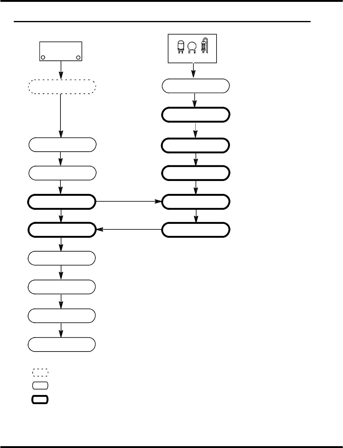
2.1 Insertion Process and Driving Transmission Flow
DA3SEC−82−120−A0
Sentence No.
PC board
PCB feed
PCB transfer
Insertion position
selection
Insertion complete
Loader conveyor
(Machine)
PCB transfer
PCB stock
Unloader conveyor
(Machine)
(Radial component)
Feeder carriage
1 pitch feed
Parts cassette
Transfer chuck
Cutter
Insertion head
Anvil
X−Y table transfer
PCB positioning
Component chucking
Component stock
Lead wire/Base
cutting
Component insertion
Lead wire cut & clinch
PCB positioning release
X−Y table origin return
BHU
=REFERENCE=
Indicates operation with optional device (BHU).
Indicates a machine operation with operating units described at the right.
Indicates a sequence of operation to be repeated for the number of components to be
inserted on a PC board.