Q170226E01.pdf - 第210页
5.33 Lead Cutter and T ape Cutter Stroke Adjustment SERVICE MANUAL RH5 5.33−1 DA3SEC−83−9R0−A0 5.33 Lead Cutter and T ape Cutter Stroke Adjustment DA3SEC−83−9R0−A0 Sentence No. When to perform x When cutting errors occur…
RH5
5.32 Setting Offset Values
SERVICE MANUAL
5.32−14
DA3SEC−83−9Q0−A0
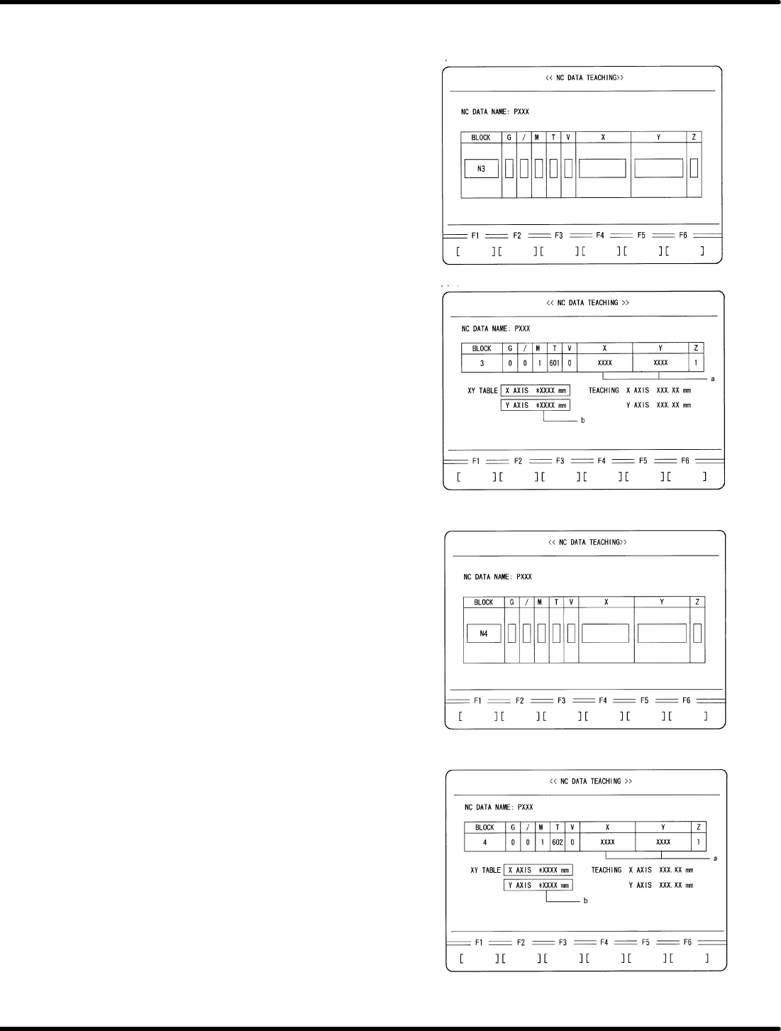
7. Move the XY table to the insertion position
of N3 block in the NC data.
x Move the cursor to N3 block using np
keys.
x Press ENTER.
x Press F1 (MOVE).
8. Check the difference between XY
coordinate (a) and XY table displacement
(b).
x Compare the XY table coordinate (a) and
the XY table displacement (b) written
down in 3. Camera Installation Position
Adjustment (6.32−5 (5)). Make sure that
the difference between these values is
within r0.03 mm.
x Check if the guide pin has been aligned
with the center of the board hole.
9. Move the XY table to the insertion position
of N4 block in the NC data.
x Press ESC.
x Move the cursor to N3 block using np
keys.
x Press ENTER.
x Press F1 (MOVE)
10. Check the difference between XY
coordinate (a) and XY table displacement
(b).
x Compare the XY table coordinate (a) and
the XY table displacement (b) written
down in 6.32−11 (3). “Automatic Camera
Offset Measuring (Y Direction)”.
Make sure that the difference between
these values is within r 0.03 mm.
x Check if the guide pin has been aligned
with the center of the board hole.
5.33 Lead Cutter and Tape Cutter Stroke Adjustment
SERVICE MANUAL
RH5
5.33−1
DA3SEC−83−9R0−A0
5.33 Lead Cutter and Tape Cutter Stroke Adjustment
DA3SEC−83−9R0−A0
Sentence No.
When to perform
x When cutting errors occur.
Required tools
x Lever−operated dial gauge
x Allen wrench
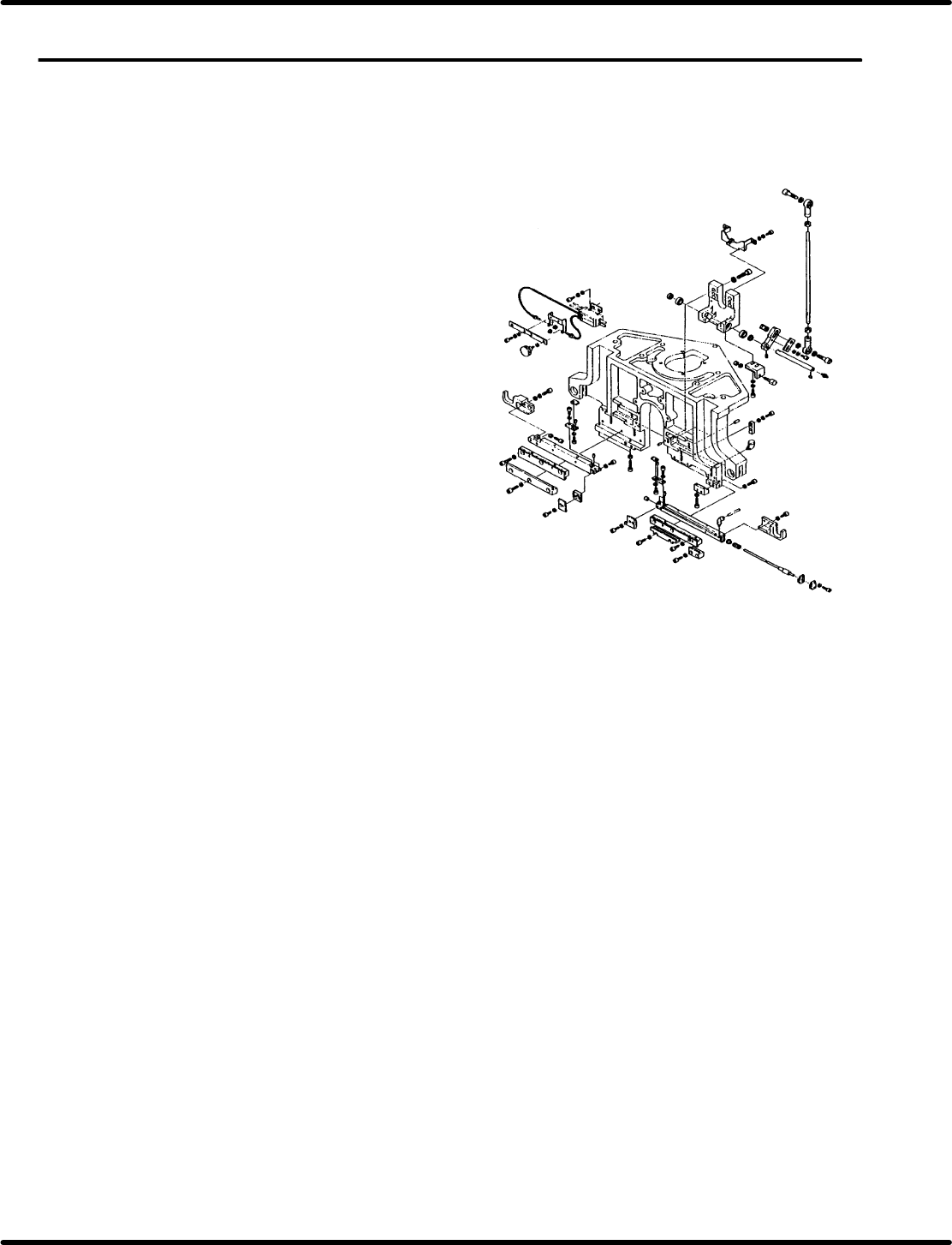
Preparations
x Move the feeder carriage to a position
where the cutter blade can be removed
easily from the rear of the machine.
x Remove the cutter blade and replace
with new ones (lead cutter, tape cutter).
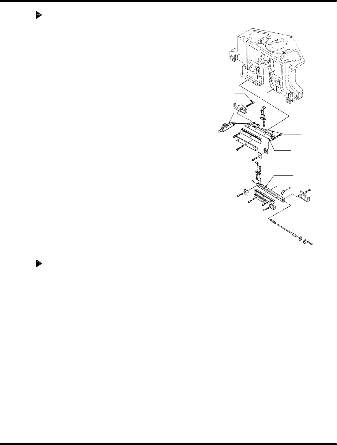
Bolt
Level−operated
dial gauge
Cutter 2
Slider
Cutter 1
A
A
RH5
5.33 Lead Cutter and Tape Cutter Stroke Adjustment
SERVICE MANUAL
5.33−2
DA3SEC−83−9R0−A0
Cam drive (Stroke adjustment of
cutter 2)
1. Disengage the bolt mounting the slide of
the cutter 2.
2. Turn the hand wheel to set the digital
sequence timer to 315q.
3. Squeeze the slider of the cutter 2 so
that the cutter 1 and 2 are lightly
engaged.
(No squeezing)
4. Lock in bolt of the cutter 2 temporality.
5. Set the digital sequence timer to 0q and
set the lever−operated dial gauge to “0”
while pressing it against the slider unit of
the cutter .
6. Disengage the bolt mounting the slider of
the cutter 2 again.
7. Squeeze the slider of the cutter 2 until the
needle of lever−operated dial gauge
indicates 0.1 mm. Then, re−tighten bolts (x
2) to secure the cutter 2.
Cam drive (Cutting check)
1. Perform a trial cutting with an actual
component to make sure that tape
wastes fall off after shaking the
component one or two times.
=CHECK=
If tape waste or lead waste failed to
be cut, check the cutter by referring
to ‘5.15 Lead/Cutter and Tape Cutter
Replacement and Adjustment’.