Q170226E01.pdf - 第251页
RH5 7.1 NC Unit Adjustment SERVICE MANUAL 7.1−4 DA3SEC−84−290−A0 7.1.3 AC Motor Power ON (1) T urn On power but make sure the safety switches stay OFF . =CHECK= In this state, keep hands on the EMERGENCY STOP at all time…

7.1 NC Unit Adjustment
SERVICE MANUAL
RH5
7.1−3
DA3SEC−84−290−A0
If the motor oscillates
1. Increase/decrease the torque command filter constant (Cn−17) in 1 increment until the oscillation is
eliminated.
2. If the oscillation persists even after the adjustment of 1) above, decrease the speed loop gain (Cn−04)
in 5 increments to eliminate the problem. At this time, measure the waveform of the speed monitor
(VTG−M) to make sure no hunting, overshoot undershoot, nor rounding in the waveform is found.
If hunting, overshoot, undershoot or rounding in the waveform exists
1. Increase the speed loop gain (Cn−04) in 5 increments to remedy the problem.
At this time, measure the waveform of the speed monitor (VTG−M) to make sure no hunting overshoot,
undershoot, nor rounding in the waveform is found.

RH5
7.1 NC Unit Adjustment
SERVICE MANUAL
7.1−4
DA3SEC−84−290−A0
7.1.3 AC Motor Power ON
(1) Turn On power but make sure the safety switches stay OFF.
=CHECK=
In this state, keep hands on the EMERGENCY STOP at all times . If the X−Y or Z tables start to
move, shut OFF power immediately.
(2) Check each table is locked into position (servolock).
This position is stored in the NC unit. If the table is some how moved, it will return to its original
position immediately.
=CHECK=
In this state, try moving the table. If it is too weak to return in position, or if the motor turns but the
table does not move, gradually raise the speed loop gain (Cn−04) of the motor drier, within the 1 to
5 range.
If the table overly shakes while returning in position gradually lower the speed loop gain (C4−04)
mentioned above, within the 1 to 5 range.
If this proves ineffective, check wiring, the AC motor driver and CNC board.
(3) Interlock activation check
Turn the safety switches (limit switches) on the X, Y and Z axes. (Only while the sensors are on,
“P−OT” and “N−OT” are alternately displayed on the motor driver monitor.
Try pushing each of the tables, checking they do not readily move. While the interlock is engaged,
even if the table moves and you remove your hand, it will not return in position.
=CHECK=
To release the interlock, turn ON the SERVOLOCK RELEASE switch and return the table to
roughly the center position. Then, press the OPERATION RESET switch and then the
SERVOLOCK RELEASE switch.
7.1 NC Unit Adjustment
SERVICE MANUAL
RH5
7.1−5
DA3SEC−84−290−A0
7.1.4 Manual Mode Movement Check in the Manual Mode
(1) Manual move teaching check in the manual mode (1 step, continuous). When moving, check the
table stops at the + and − limits.
(2) Manual mode origin return check
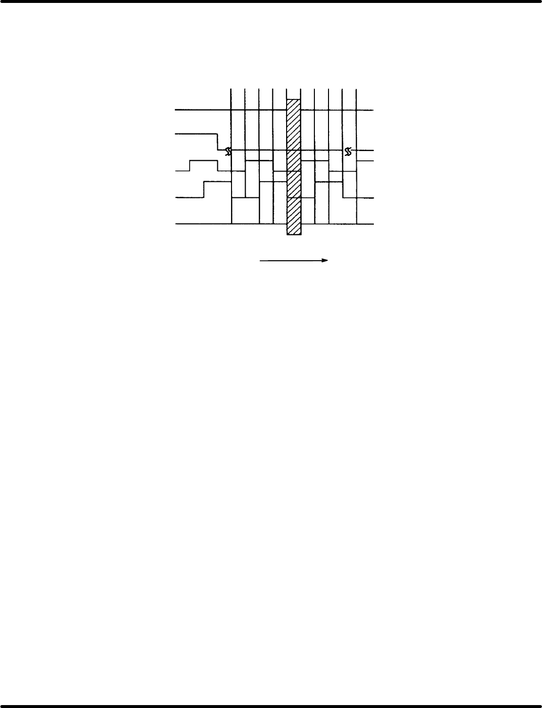
Table origin monitor
Table origin signal
Pulse generator A phase
Pulse generator B phase
Pulse generator C phase
When turns CCW
0 1 2 3 0 phase 1 2 3 0
Figure 7.1−5−
=CHECK=
x When the X−Y−Z ORG switch is pressed, all three axes return to their respective origins.
x When the table are back at their origins, check the table origin signal and origin slow signal are at
the center of the table origin monitor.
x The Z phase signal is generated once every time monitor rotates once.