Q170226E01.pdf - 第124页
5.7 Insertion Head Insertion Pusher Perpendicularity/Height Check/Adjustment SERVICE MANUAL RH5 5.7−1 DA3SEC−83−8PO−A0 5.7 Insertion Head Insertion Pusher Perpendicularity/Height Check/Adjustment DA3SEC−83−8PO−A0 Sentenc…
RH5
5.6 Insertion Head Guide Parallelism Check and Adjustment
SERVICE MANUAL
5.6−2
DA3SEC−83−8N0−A0
Adjusting parallelism
1. Loosen the bolt on the insertion head drive unit.
Then, while pressing down on the arm by hand,
turn the cam follower guide until the correct
degree of parallelism is obtained.
2. After making adjustment, tighten the arm bolt to
check for the parallelism again.
=CHECK=
Be careful not to change the arm height when
tightening the arm bolt because the arm
moves up/down easily during adjustment.
Cam follower
guide
Arm
Bolt
5.7 Insertion Head Insertion Pusher Perpendicularity/Height Check/Adjustment
SERVICE MANUAL
RH5
5.7−1
DA3SEC−83−8PO−A0
5.7 Insertion Head Insertion Pusher
Perpendicularity/Height Check/Adjustment
DA3SEC−83−8PO−A0
Sentence No.
When to perform
x When parts are often slanted or
squashed following insertion.
x When parts are dropped frequently
during insertion.
x When insertion errors occur
frequently.
x Allen wrench
x L−square
x Lever−operated dial gauge
Required tools
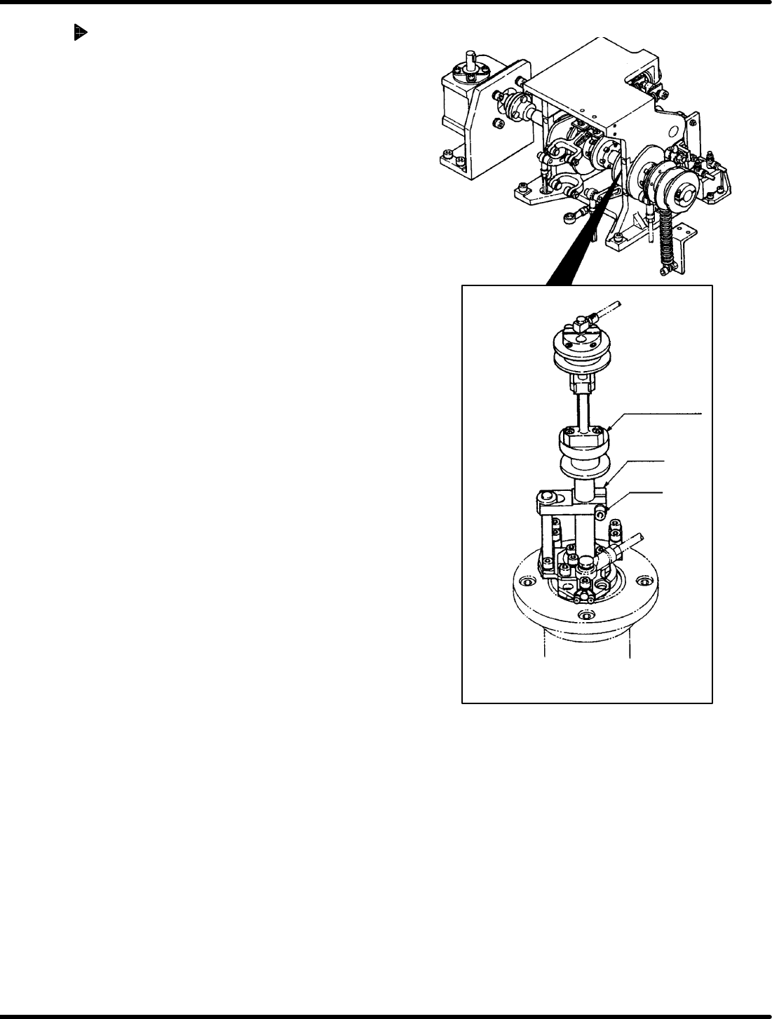
Perpendicularity check
1. Remove the guide chuck and press the dial
gauge against the side of the insertion pusher
to make sure the perpendicularity is within 0.1
mm.
=CHECK=
When lifting the pusher with your finger,
make sure that the pusher moves
smoothly.
(If not so, remove the spring pin from the
pusher and ream the inside of the pusher
rod with a straight reamer between I6.0
and I6.02.)
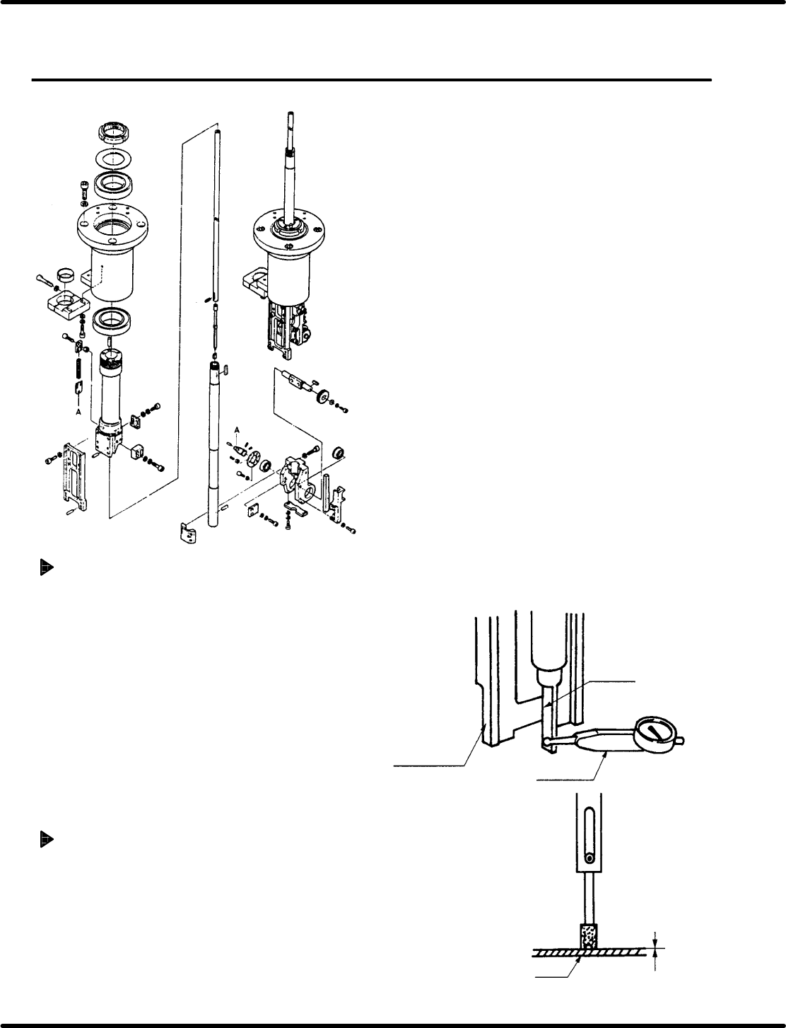
Height check
1. Using the hand wheel, set the sequence timer
to 310q (pusher lower limit) and make sure the
distance between the pusher and PC board is
between 0 and 0.5 mm.
Pusher
Dial gauge
Guide chuck
frame
PCB
Within: 0 − 0.5 mm
RH5
5.7 Insertion Head Insertion Pusher Perpendicularity/Height Check/Adjustment
SERVICE MANUAL
5.7−2
DA3SEC−83−8PO−A0
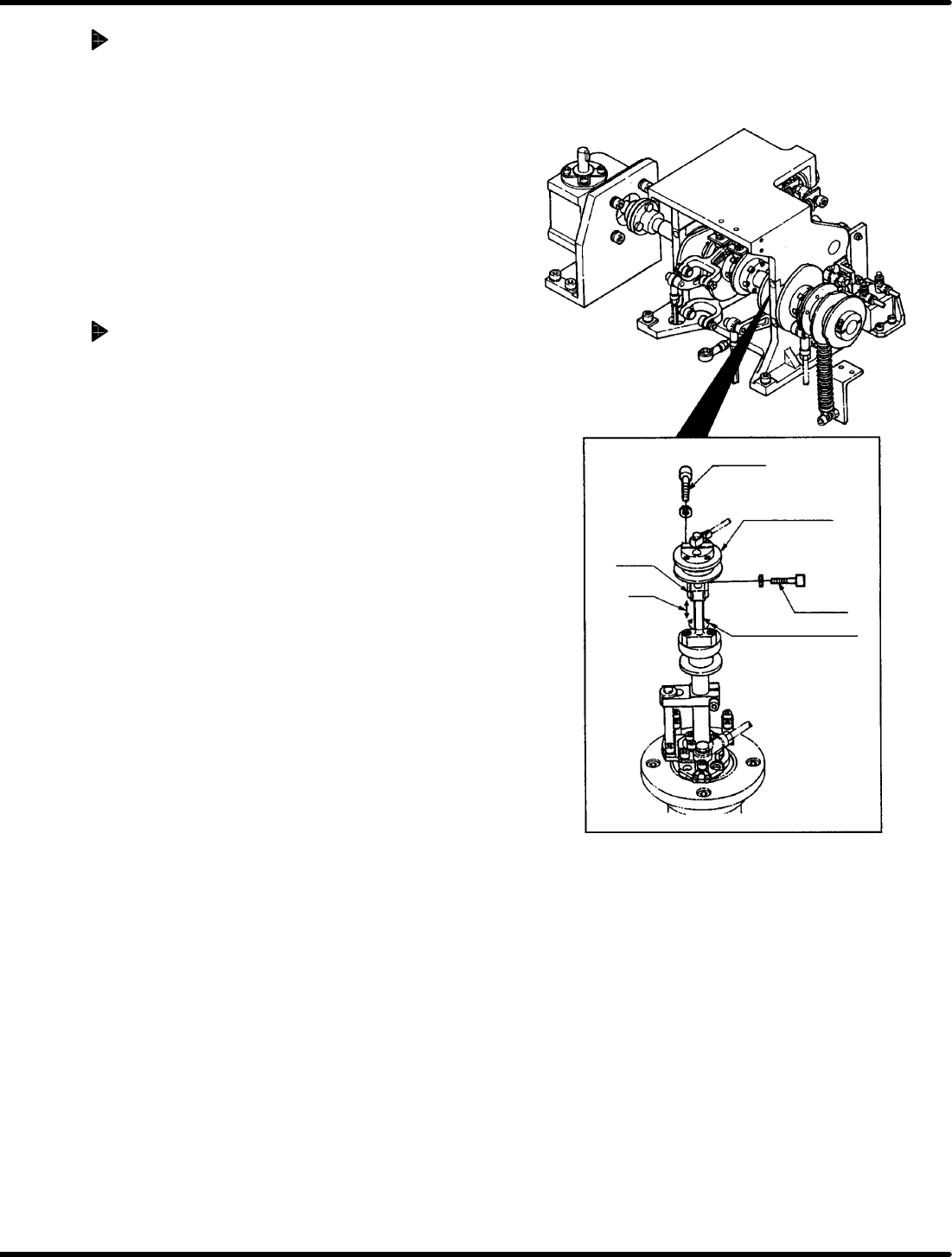
Adjusting perpendicularity
1. Loosen the bolt B and disengage the arm.
Then turn the shaft to measure the
perpendicularity.
(Adjust the perpendicularity within 0.1 mm.)
=CHECK=
As the bolt B is also fixed with cotter, tap
it lightly to release after loosening the
bolt.
(Be careful not to drop the arm after the
cotter released.)
Adjusting height
1. Disengage the bolt A (x 2).
2. Move the pusher rod up/down so that the gap
between it and the PC board (t = 1.6) may be
between 0 and 0.5 mm.
=CHECK=
When lifting the pusher rod, loosen the
bolt B to raise the pusher and then
retighten the bolt B. Check that the
perpendicularity does not change when
loosening the bolt B.
Bolt A
Bolt B
Cam follower
guide
Perpendicularity
Arm
Height