Q170226E01.pdf - 第272页
7.2 AC Servomotor Adjustment SERVICE MANUAL RH5 7.2−17 DA3SEC−84−300−A0 ( Camshaft ) Parameter No. Name Default Cn−00−0003 Offset Cn−01 Memory switch 1 0000000000001 100 Cn−02 Memory switch 2 0000000000000000 Cn−03 Speed…

RH5
7.2 AC Servomotor Adjustment
SERVICE MANUAL
7.2−16
DA3SEC−84−300−A0
Z axis (80−feeder)
Parameter
No.
Name Default
Cn−00−0003 Offset
Cn−01 Memory switch 1 * 0001000000001100
Cn−02 Memory switch 2 0000000000000000
Cn−03 Speed command gain 1400
Cn−04 Speed loop gain (180)
Cn−05 Constant speed loop integrated *50
Cn−06 Emergency stop torque 269
Cn−07 Soft start time (acceleration) 0
Cn−08 Normal rotation torque limit 269
Cn−09 Reverse rotation torque limit 269
Cn−0A Encoder pulse dividing ratio 640
Cn−0B Rotation detection level 20
Cn−0C Mode switch (torque command) * 200
Cn−0D Mode switch (speed command) *50
Cn−0E Mode switch (acceleration command) 0
Cn−0F Zero clamp level 10
Cn−10 JOG speed 100
Cn−11 Encoder pulse count 2048
Cn−12 Delay time from brake command to SV OFF 20
Cn−13 Torque command gain 30
Cn−14 Speed control at torque control I 4000
Cn−15 Speed level at which output brake command 100
Cn−16 Wait time from SV OFF to brake command 50
Cn−17 Torque command filter constant (15)

7.2 AC Servomotor Adjustment
SERVICE MANUAL
RH5
7.2−17
DA3SEC−84−300−A0
( Camshaft )
Parameter
No.
Name Default
Cn−00−0003 Offset
Cn−01 Memory switch 1 0000000000001100
Cn−02 Memory switch 2 0000000000000000
Cn−03 Speed command gain 1400
Cn−04 Speed loop gain (180)
Cn−05 Consult speed loop integrated 1000
Cn−06 Emergency stop torque 344
Cn−07 Soft start time (acceleration) 0
Cn−08 Normal rotation torque limit 344
Cn−09 Reverse rotation torque limit 344
Cn−0A Encoder pulse dividing ratio 1000
Cn−0B Rotation detection level 20
Cn−0C Mode switch (torque command) 200
Cn−0D Mode switch (speed command) 0
Cn−0E Mode switch (acceleration command) 0
Cn−0F Zero clamp level 10
Cn−10 JOG clamp level 100
Cn−11 Encoder pulse count 4096
Cn−12 Base block waiting time 0
Cn−13 Torque command gain 30
Cn−14 Speed control at torque control I 10000
Cn−15 Speed level at which output brake command 100
Cn−16 Wait time from SV OFF to brake command 50
Cn−17 Torque command filter constant (4)
RH5
7.2 AC Servomotor Adjustment
SERVICE MANUAL
7.2−18
DA3SEC−84−300−A0
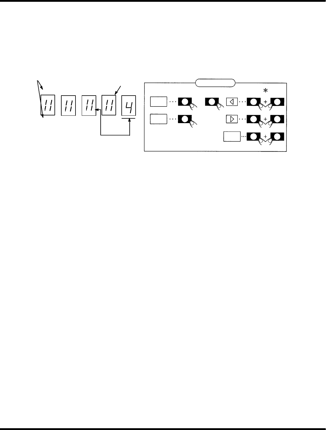
7.2.5 Setting/Browsing User Constant (Memory Switch)
(Cn−01 and Cn−02)
User constants Cn−01 and Cn−02 can be set or browsed by bits as a memory switch.
Figure 7.2−1 shows the functions of switches after the bit data is displayed.
To change Cn−01 or Cn−02 (User constants), turn ON the control power to enable the preset functions.
Panel display
EC A B6 42 0
FD B 97 53 1
SW2 SW1 SW3
SW4 SW1 SW3
SW1 SW3
DATA
bit
SET
Bit No.
Light up when ON
bit No. to be set
* Show that SW2 (SW3 or SW4) shall be pressed
while holding SW1 down.
or
Switch function
Figure 7.2−1− Function Switches
1. Using the arrow keys, set the bit No. of the memory switch to be set to the right end of the panel.
2. Using “bit” key, turn ON/OFF the memory switch. (Either SW2 or SW3 is permissible.)
(The lamp lights up when ON and goes out when OFF.)
3. Repeat steps 1 and 2 as necessary.
4. Press “SET” to store data.
5. Press “DATA” to return to the screen.
6. Press “SET” to switch to the monitor mode.
Here following describes the functions of the memory switches of the user constants Cn−01 and Cn−02.