Q170226E01.pdf - 第387页
RH5 8.10 R e m o v i ng Ba tt er y fr om Co nt r oller (Panadac 791) SERVICE MANUAL 8.10 − 2 DA3SEC − 85 − 530 − A0 Removing Battery MIOE (I) card (contains battery) Screw Front cover 1. Open the front right door of the …
8.10 Removing Battery from Controller (Panadac 791)
SERVICE MANUAL
RH5
8.10−1
DA3SEC−85−530−A0
8.10 Removing Battery from Controller (Panadac 791)
DA3SEC−85−530−A0
Sentence No.
=REMARKS=
The product that you have purchased contains a rechargeable battery. The battery is recyclable.
At the end of its useful life, under various state and local laws, it may be illegal to dispose of this
battery into the municipal waste stream. Check with your local solid waste officials for details in
your area for recycling options or proper disposal.
(Panadac P791)
RH5
8.10 Removing Battery from Controller (Panadac 791)
SERVICE MANUAL
8.10−2
DA3SEC−85−530−A0
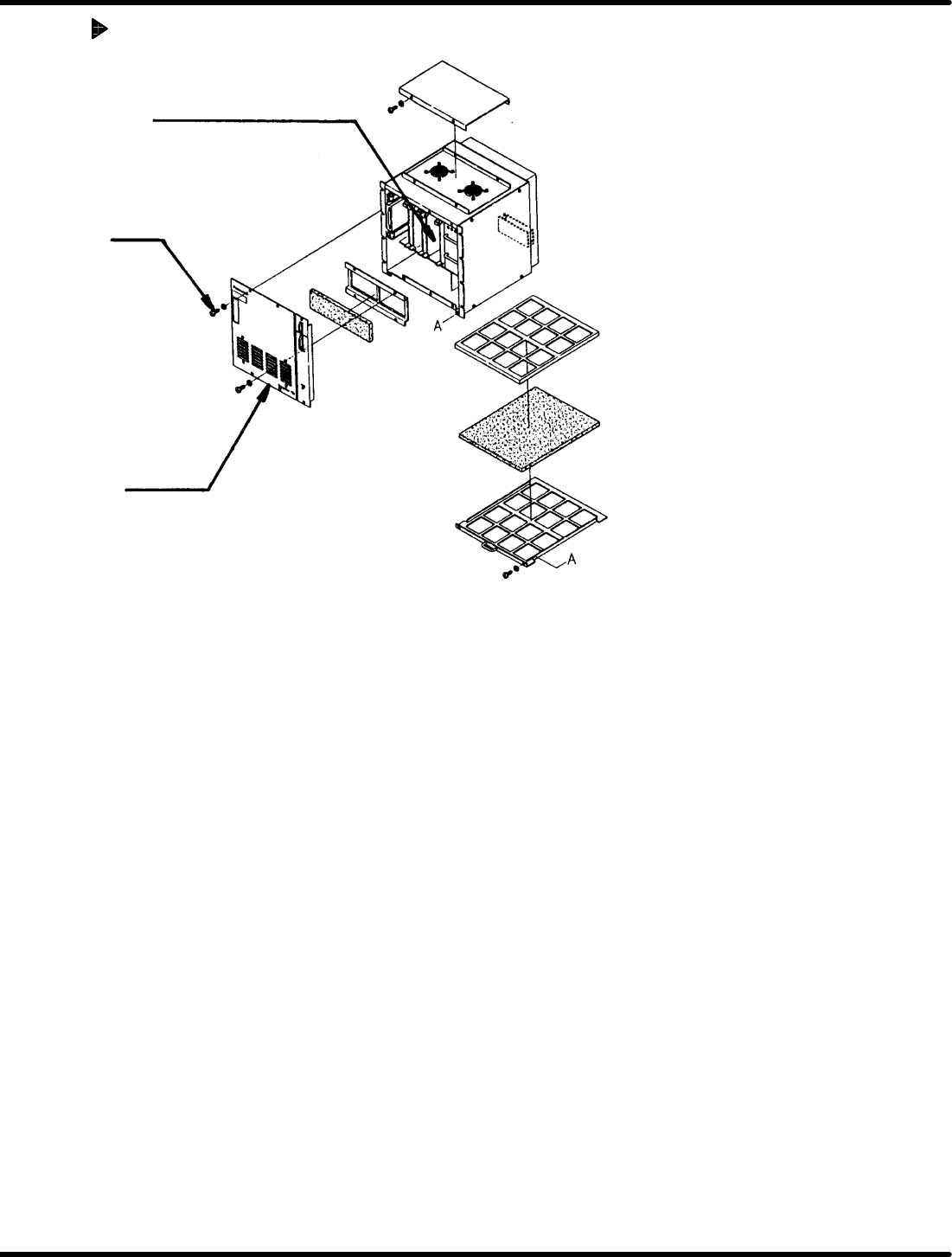
Removing Battery
MIOE (I) card (contains battery)
Screw
Front cover
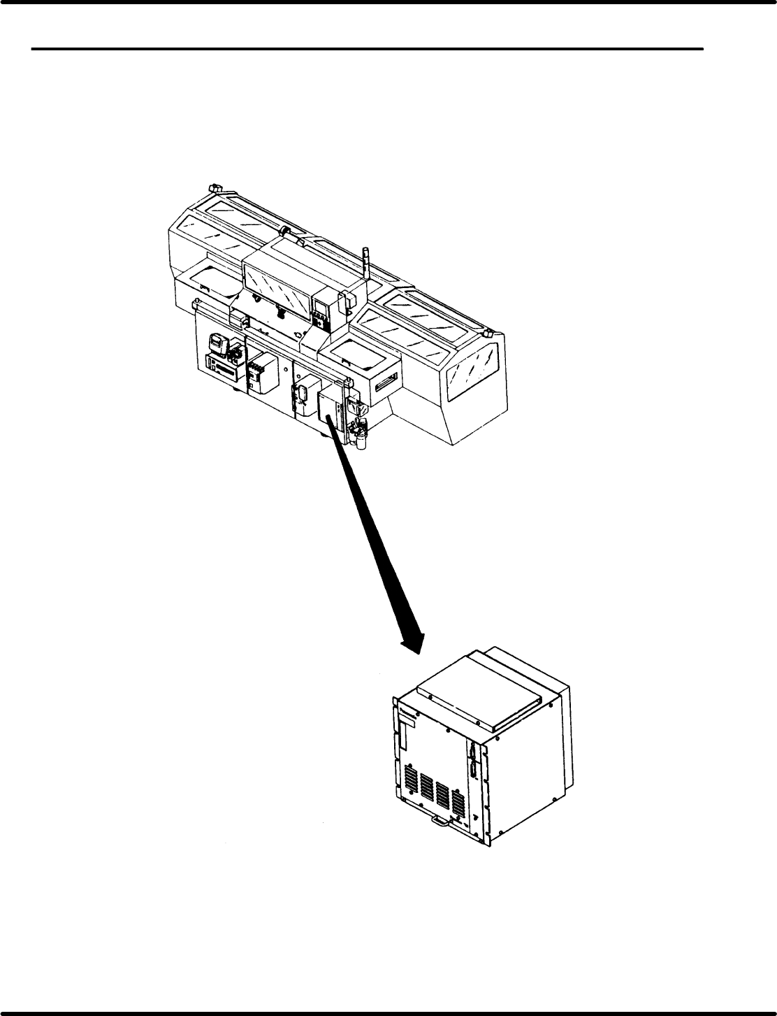
1. Open the front right door of the equipment.
2. Remove four screws of the Panadac 791 to detach the front cover.
3. Remove two screws of the fixture securing the MIOE (I) card in the 11th slot of the Panadac 791.
4. Draw out the MIOE (I) card from the slot and remove the battery using nippers or unsolder the battery
for removal.
=CHECK=
x Contact our service personnel for proper replacement of the battery.
x Be sure to save necessary data for backup before replacing the battery.
x Make sure that power to the machine is OFF before performing the above work.
8.11 Differences in Specifications between RHIII and RH5
SERVICE MANUAL
RH5
8.11−1
DA3SEC−85−X10−A0
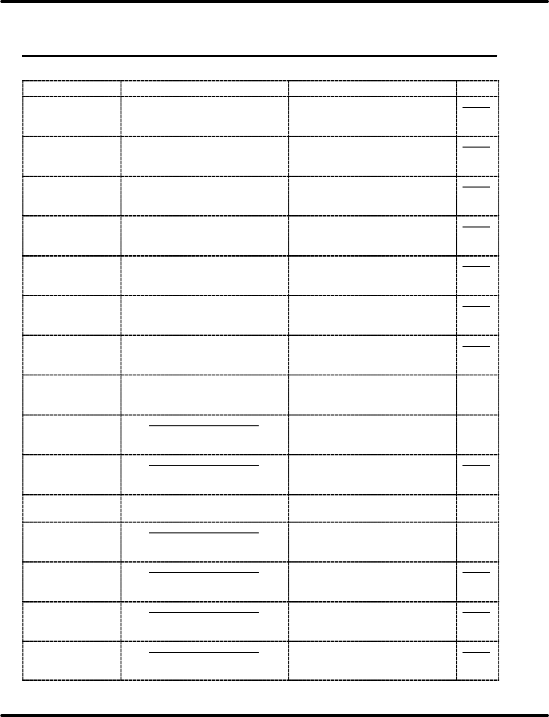
8.11 Differences in Specifications between RHIII and
RH5
DA3SEC−85−X10−A0
Sentence No.
Item RHIII RH5
Remarks
Loader unit
(PCB transfer and
pneumatic system)
Loading time
M: 3.5 s
LL: 4.5 s
Stoppers added and changed
M: 2.5 s
LL: 4.5 s
Loader unit
(PCB transfer and
pneumatic system)
Cylinder changed
I6
Cylinder strength enforced
I8
Unloader unit
(PCB transfer and
pneumatic system)
Loading time
M: 3.5 s
LL: 4.5 s
Stoppers added and changed
M: 2.5 s
LL: 4.5 s
Unloader unit
(PCB transfer and
pneumatic system)
Cylinder changed
I6
Cylinder strength enforced
I8
Piping unit
(PCB transfer and
pneumatic system)
35 mm s
Solenoid valve response improved
15 mm sec
(Changed to VQZ)
Main drive
(Motor)
2.0 kw
AC servomotor capacity increased
3.0 kw
(Reduction ratio changed)
Guide pin select unit
(Structure
improved)
Guide pin select unit:
swivel system
Guide pin unit:
Swivel mechanism abolished o
Lock system
Upper drive unit
(Structure
improved)
Cam timing
sequence timing
Mechanical valve timing
Altered
Altered
Altered
2.6
Upper drive unit
(Lock stabilized)
Lock cylinder stroke & support pin
changed
(for easy adjustment)
2.9
Upper drive unit
(Maintainability
improved)
Grease nipples added to the lever
bearings
Lower drive unit
(Lock stabilized)
Cam timing
sequence timing
Altered
Altered
2.6
Lower drive unit
(Lock stabilized)
Lock cylinder stroke & support pin
changed
(for easy adjustment)
2.9
Lower drive unit
(Maintainability
improved)
Grease nipples added to the lever
bearings
Parts feeder unit
(Feed position
stabilized)
Feed position structure improved
(Feed stabilized)
Parts feeder unit
(Feed position
stabilized)
Stopper added for preventing feed
pusher overrun