Q170226E01.pdf - 第278页
7.3 Digital Operator SERVICE MANUAL RH5 7.3−1 DA3SEC−84−310−A0 7.3 Digital Operator DA3SEC−84−310−A0 Sentence No. 7.3.1 Inputting Offset V alue (Cn−00) Display Procedure Remarks 1 [Menu] Select the check function F1: NC …
RH5
7.2 AC Servomotor Adjustment
SERVICE MANUAL
7.2−22
DA3SEC−84−300−A0
Selected
item
Bit
No.
De−
fault
Description Command input Sequence
signal input
Refer−
ence
Control
mode
B/A 1/1
Motor speed
IN−A
Speed control
range
In torque control:
Torque command (IN−B)
Speed limit (IN−A)
In speed control:
Speed command (IN−A)
=REFERENCE=
x Outside the limit
speed range, the
torque proportional to
the difference with the
limit speed is fed back
negatively to take
P−CON
OFF: Torque
control
ON: Speed
control
0/0
When controlling speed:
x Input speed command
from IN−A.
x IN−B cannot be used.
gy
back the speed to
within the limit range.
Therefore, the motor
speed limit value
varies according to
the load condition.
x Contact us the motor
speed decreases
continuously by
torque command
=REFERENCE=
Cn−02: Reserved
User Constant Cn−02 (Memory Switch) List
Selected
item
Bit No. De−
fault
Description Reference
Reverse turn mode 0 0 Set the normal turn in CCW direction. 0
1 Set the normal turn in CW direction.
Encoder error 1
SR
BY
l
0 Detects encoder trouble. 0
SR BY only
1 Does not detect encoder trouble.
Reserved 2−F Do not set.
7.3 Digital Operator
SERVICE MANUAL
RH5
7.3−1
DA3SEC−84−310−A0
7.3 Digital Operator
DA3SEC−84−310−A0
Sentence No.
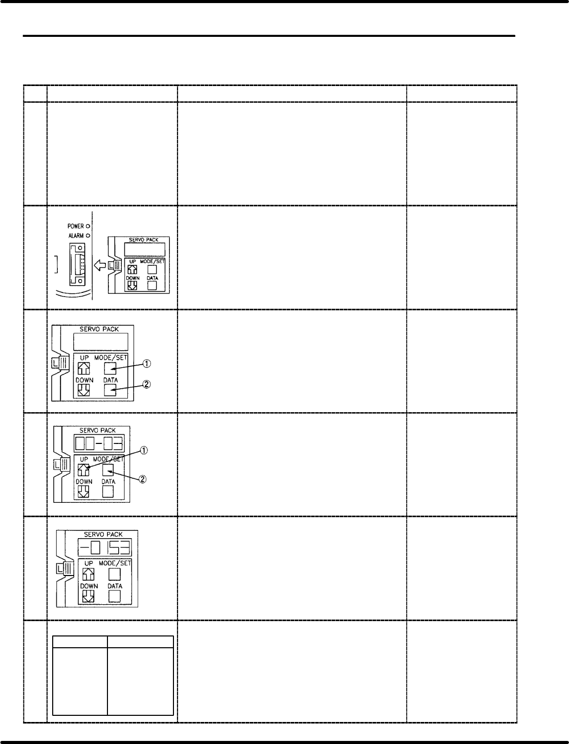
7.3.1 Inputting Offset Value (Cn−00)
Display Procedure Remarks
1 [Menu]
Select the check function
F1: NC axis jog check
F2: NC axis move check
F3: NC data teaching
Press “F1” (NC AXIS JOG CHECK) after pressing
ORG in manual, 1 block mode.
2 Set the digital operator to the desired driver. x Setting the digital
operator changes the
display to “run”.
3 Press MODE/SET key to change the display to Cn−00
and then press DATA key to change to 00−00.
4
Press
three
times.
Press UP key three times to display to 00−03 and
then press MODE/SET for 4−digit numerics.
5 Pressing UP key increases the value and Down key
decreases the value. Using UP and DOWN keys, set
the monitor display to r0.00 mm.
6
[NC axis JOG check]
NC axis Present position
XY table X=+0.00 mm
Y=+0.00 mm
Z axis (casette) 0.00 mm
Loader width
adjustment *****
Unloader width
adjustment *****
Table width
adjustment *****
Press “SEMI” − “1BLOCK” − “RESET” and “START”
and move the X/Y/Z axis. Then press “MANU” −
“1BLOCK” − “ORG.” and “F1” (NC AXIS JOG CHECK)
to make sure each axes indicates r0.00 mm.
xThe values other than
r0.00 mm, shall be
adjusted to r0.00 mm
using UP and DOWN
keys.
RH5
7.3 Digital Operator
SERVICE MANUAL
7.3−2
DA3SEC−84−310−A0
Display Procedure Remarks
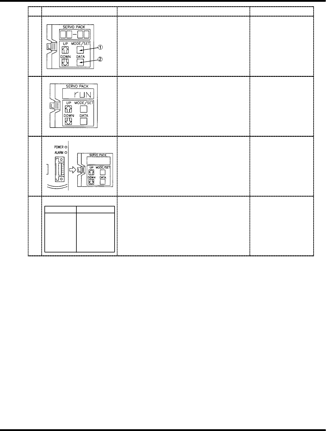
7 Press MODE/SET key to change the display to Cn−03
and then press DOWN key three times to change to
00−00.
8 Press DATA key to change the display to Cn−00 and
then press MODE/SET to change to “run”.
9 Remove the digital operator from the driver and turn
OFF the power to the machine once.
10
[NC axis JOG check]
NC axis Present position
XY table X=+0.00 mm
Y=+0.00 mm
Z axis (casette) 0.00 mm
Loader width
adjustment *****
Unloader width
adjustment *****
Table width
adjustment *****
Turn the power back ON and press “F1” (NC JOG
CHECK) to make sure the each axis are set to r0.00
mm.
x The values other than
r0.00 mm shall be
adjusted to, set to r0.00
mm using UP and
DOWN keys.