Q170226E01.pdf - 第131页
RH5 5.10 Insertion Head Transfer Chuck Claw/Rubber Replacement/Adjustment SERVICE MANUAL 5.10−2 DA3SEC−83−8SO−A0 = MEMO =
5.10 Insertion Head Transfer Chuck Claw/Rubber Replacement/Adjustment
SERVICE MANUAL
RH5
5.10−1
DA3SEC−83−8SO−A0
5.10 Insertion Head Transfer Chuck Claw/Rubber
Replacement/Adjustment
DA3SEC−83−8SO−A0
Sentence No.
When to perform
x When inserted parts are often
slanted.
x When insertion errors occur
frequently.
x Allen wrench
Required tools
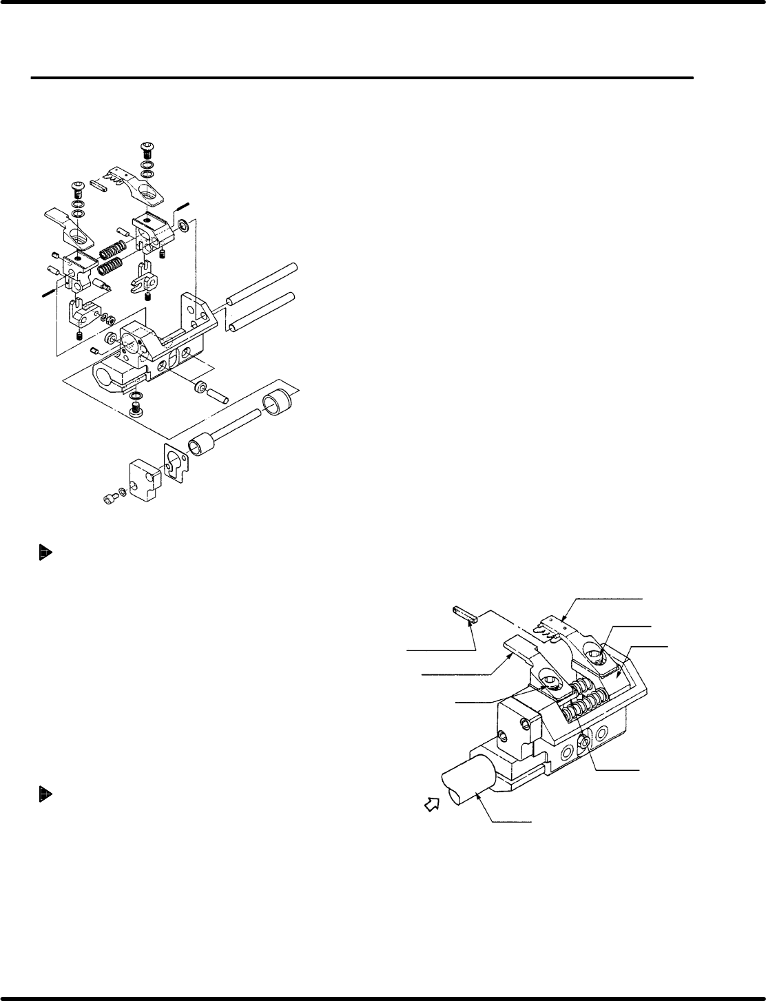
Chuck claw replacement
1. Remove bolts A (x 1) and B (x 1) fixing
chuck claws A and B in place.
2. While holding down the new claws against
the levers, fix them in place with bolts A (x 2)
and B (x 2).
=CHECK=
x Check the claws do not contact parts
when closed.
x Check the claws do not contact parts
when the transfer chuck turns 100q.
Chuck rubber replacement
1. Remove the rubber from the chuck claws.
=REFERENCE=
The rubber pops out easily.
2. Attach a new rubber.
Chuck rubber
Chuck claw B
Bolt B
Lever B
Lever A
Chuck claw B
Bolt B
Rotation
axis
Air

RH5
5.10 Insertion Head Transfer Chuck Claw/Rubber Replacement/Adjustment
SERVICE MANUAL
5.10−2
DA3SEC−83−8SO−A0
= MEMO =
5.11 Insertion Head Center Position Check and Adjustment
SERVICE MANUAL
RH5
5.11−1
DA3SEC−83−8TO−A0
5.11 Insertion Head Center Position Check and
Adjustment
DA3SEC−83−8TO−A0
Sentence No.
When to perform
x When inserted parts are often slanted.
x When insertion errors occur frequently.
Required tools
x Allen wrench
x T−wrench
x Lever−operated dial gauge
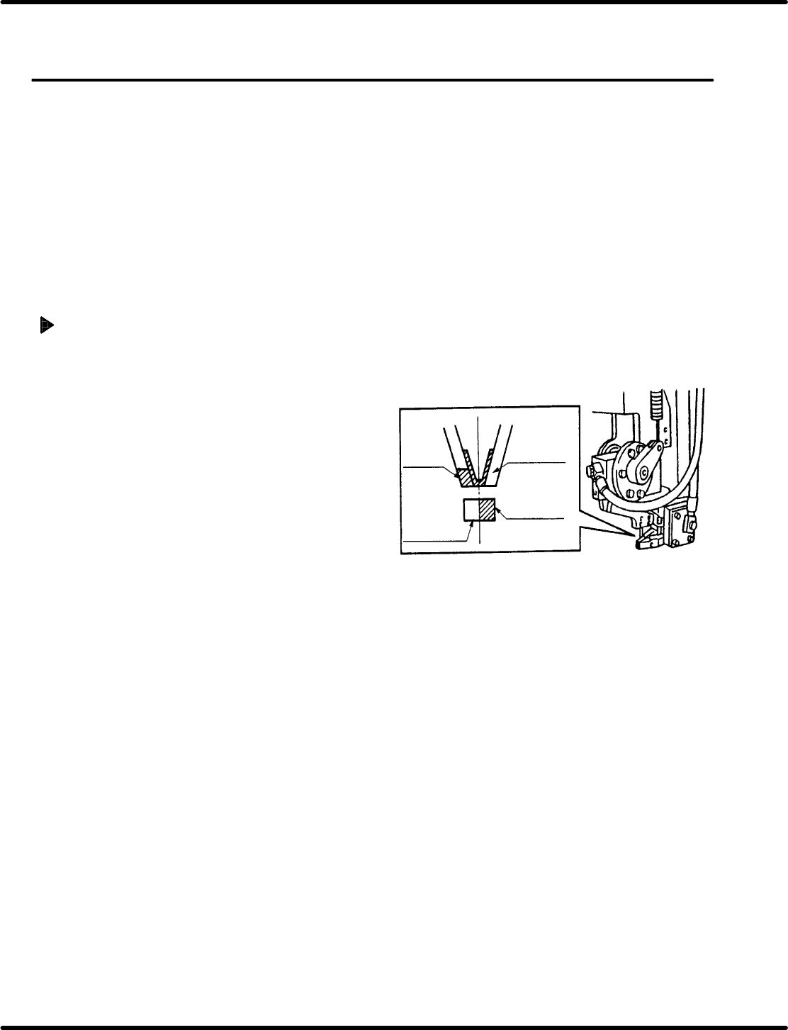
Guide chuck and insertion chuck
centering check
1. Turn the hand wheel until the cam shaft is
approximately at the 210q position on the
digital sequence timer.
=REFERENCE=
Use the guide chuck as a reference when
centering the insertion chuck, transfer
chuck, cutter and parts feeder .
2. Paint the side surface of the insertion chuck
and guide chuck white. Then visually check
the centering.
=CHECK=
Paint only one side of each chuck.
Insertion
chuck
Paint this
part white
Paint this
part white
Guide chuck