Q170226E01.pdf - 第156页
5.17 Anvil Insertion Detection Amplifier Check SERVICE MANUAL RH5 5.17−1 DA3SEC−83−8ZO−A0 5.17 Anvil Insertion Detection Amplifier Check DA3SEC−83−8ZO−A0 Sentence No. When to perform x When insertion detection errors occ…

RH5
5.16 Replacing Anvil Distortion Gauge
SERVICE MANUAL
5.16−6
DA3SEC−83−8YO−A0
= MEMO =
5.17 Anvil Insertion Detection Amplifier Check
SERVICE MANUAL
RH5
5.17−1
DA3SEC−83−8ZO−A0
5.17 Anvil Insertion Detection Amplifier Check
DA3SEC−83−8ZO−A0
Sentence No.
When to perform
x When insertion detection errors occur
frequently.
x After replacing the distortion gauge
Required tools
x Slotted screwdriver (For varistor adjustment)
x Digital voltmeter
x Oscilloscope
Power supply voltage check
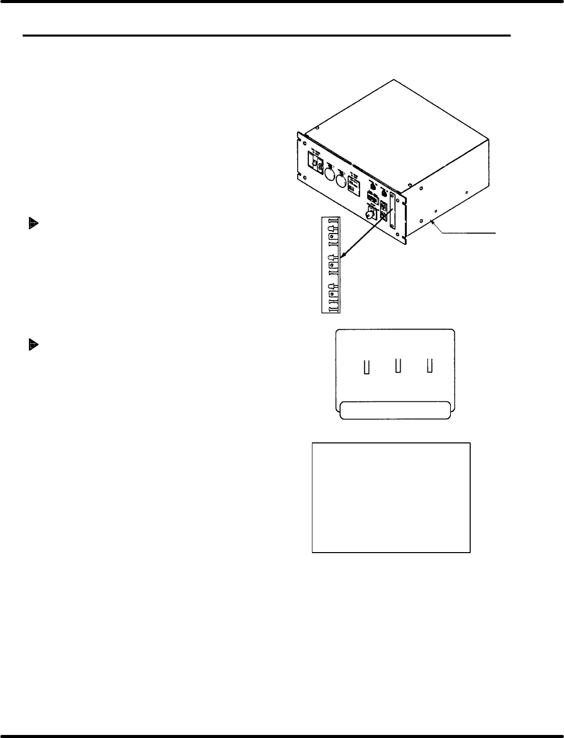
1. Remove the cover from the power source
unit
2. Check power supply voltage between 5 pin
(+5V) and 6 pin (0V)of CHU OUT (CN2 on
insertion detection amplifier board with the
voltmeter.
Distortion gauge amplifier board
jumper setting
1. Remove the distortion gauge amplifier board
from the power source unit, and select
clinch method (N or T clinch) with jumper
setting.
=REFERENCE=
x N clinch
JP1: 2 − 3 short
JP2: 2 − 3 short
JP3: 1 − 2 short
x T clinch
JP1: 1 − 2 short
JP2: 1 − 2 short
JP3: 2 − 3 short
Power source
unit
Reference 2.5 5.0
Ch1 3 2
Relation between distortion
gauge and insertion pitch
I/O address
Ch1: 0064
Ch2: 0065
Ch3: 0066
Panadac−791
RH5
5.17 Anvil Insertion Detection Amplifier Check
SERVICE MANUAL
5.17−2
DA3SEC−83−8ZO−A0
Distortion gauge amplifier board
sensitivity check
1. Remove the cover of the distortion gauge
amplifier board on the power source unit and
connect an oscilloscope to the check pin TP1
and TPGND of the board.
2. Set the range of the oscilloscope at around
1V/Div and 50 mS/Div.
3. Edit the NC data so that component insertion is
enabled. (Do not set a board.)
4. Execute the edited NC data in SEMIAUTO
mode up to the block involving component
insertion.
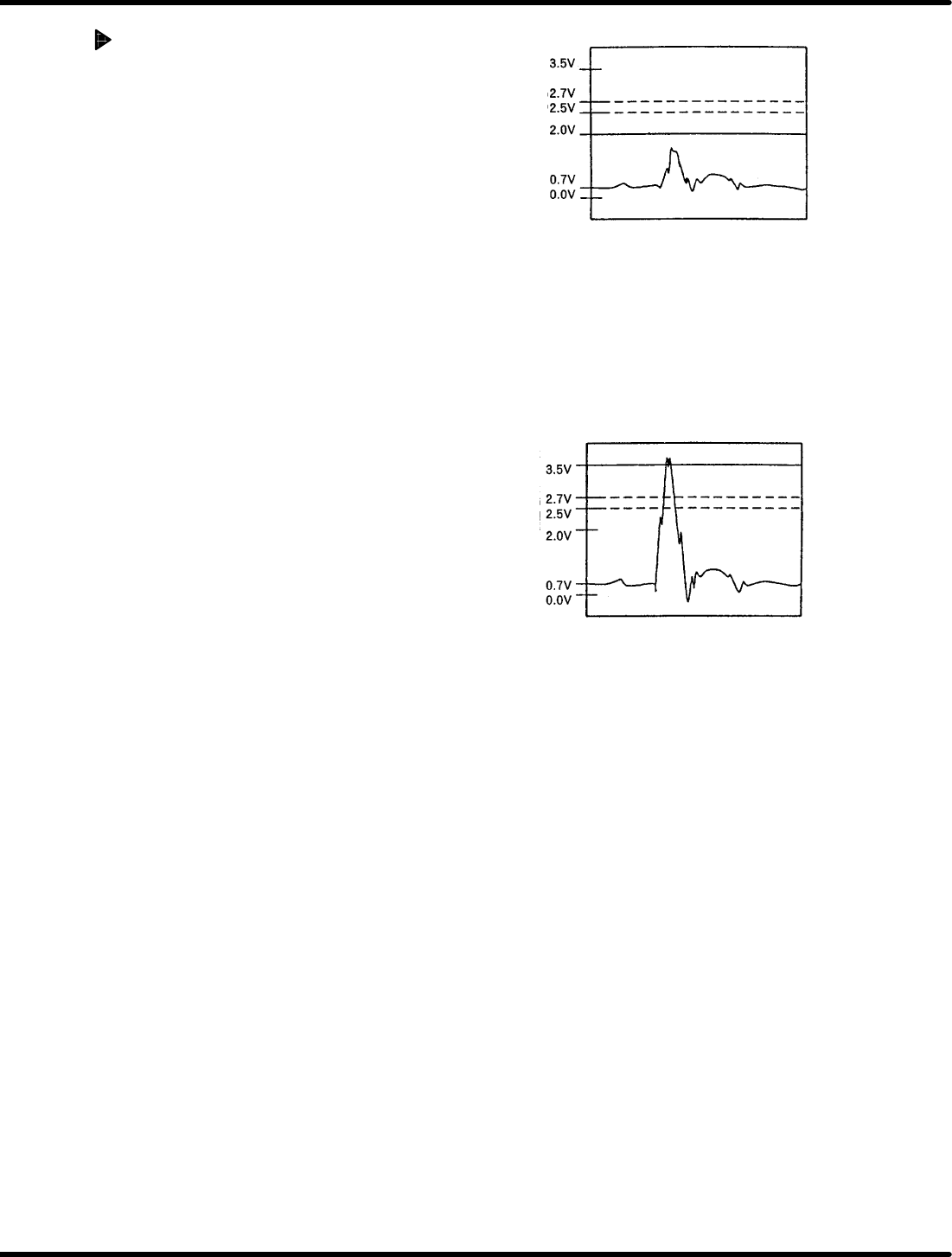
5. Adjust the volume VR1 so that the waveform of
the oscilloscope is below 2V when idling the
cam shaft in semi auto cam rotation.
=CHECK=
x The volume can be adjusted between max.
and min. by approx. 20 turns, and it can be
further turned even after reaching the max.
or min. position.
x The sensitivity of the volume decreases in
clockwise turn and increases in
counterclockwise turn.
x If the volume does not read 2V or less,
check the fixed and movable blades for
any contact.
6. Repeat step 5 for TP2 (VR2) and TP3 (VR3)
7. Set a board and check that the waveform of the
oscilloscope is below 2V when idling the cam
shaft in SEMIAUTO mode.
=CHECK=
If the waveform is more than 2V, check the
anvil and board for contact.
8. Check that waveform of the oscilloscope
exceeds 3.5 V when an electronic component is
inserted in SEMIAUTO mode.
=CHECK=
x Use electronic components with soft cooper
wire of I 0.45 mm in diameter.
x When the waveform is below 3.5, adjust the
volume VR1 to make it exceed 3.5 V.
x If the volume is adjusted, repeat steps 7
and 8 and check that the
above−mentioned waveforms can be
observed.
9. Repeat steps 7 and 8 for TP2 (VR2) and TP3
(VR3).
Figure 5.17−1− Waveform in idling
On voltage
OFF voltage
Reference
voltage
Figure 5.17−2− Waveform in component insertion
On voltage
OFF voltage
Reference
voltage