Q170226E01.pdf - 第171页
RH5 5.21 Selector Unit Lead Guide Pin Replacement SERVICE MANUAL 5.21−4 DA3SEC−83−9D0−A0 = MEMO =
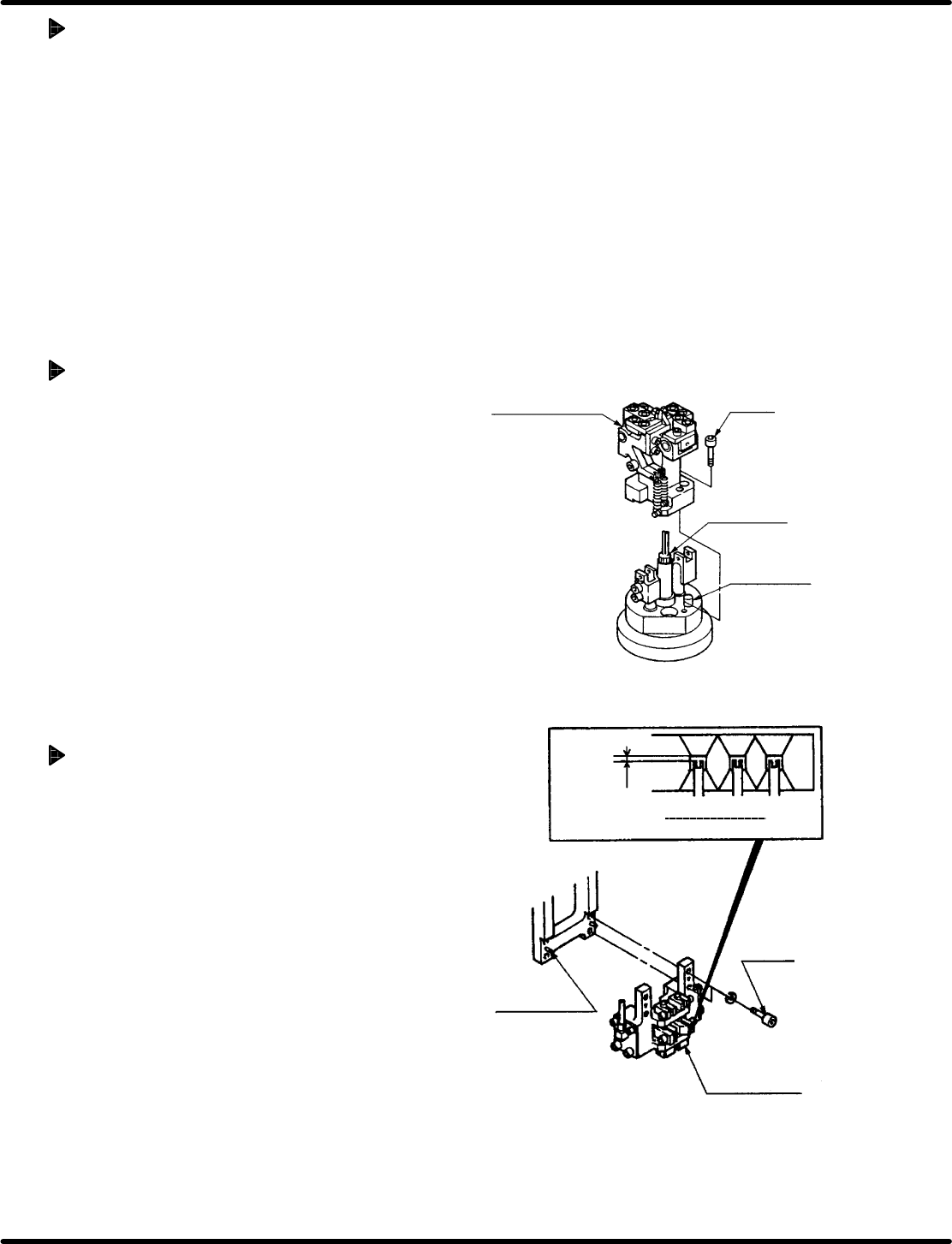
Cut & clinch body
Bolt B
Guide rod
Positioning pin
Allowable
range
0.3 − 0.5
mm
Guide pin
height
Bolt A
Positioning pin
Guide chuck
5.21 Selector Unit Lead Guide Pin Replacement
SERVICE MANUAL
RH5
5.21−3
DA3SEC−83−9D0−A0
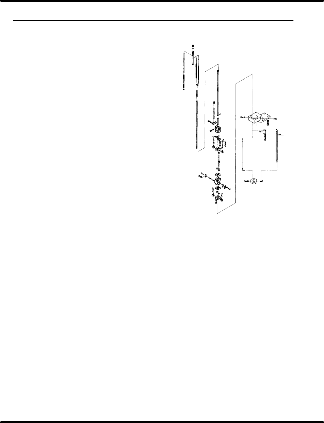
Setting the cartridge
1. Attach the cartridge to the guide pin rod.
2. Tighten the installation nut fixing the
cartridge in place.
=REFERENCE=
T ighten the installation nut fixing the
cartridge with the nipper not to be
loosened by hand.
Setting the cut & clinch body
1. Align the cartridge with the positioning pin and
fix it in place with bolt B (x 2).
Setting the guide chuck unit
1. Align the guide chuck unit with the
positioning pin and attach it.
2. Check that the guide pin height is correct
and in the correct position. Then fix it in
place with bolt A (x 4).

RH5
5.21 Selector Unit Lead Guide Pin Replacement
SERVICE MANUAL
5.21−4
DA3SEC−83−9D0−A0
= MEMO =
5.22 Selector Unit Selector Rod Replacement
SERVICE MANUAL
RH5
5.22−1
DA3SEC−83−9E0−A0
5.22 Selector Unit Selector Rod Replacement
DA3SEC−83−9E0−A0
Sentence No.
When to perform
x When selection performance deteriorates due
to rod wear or damage.
Required tools
x Allen wrench