Q170226E01.pdf - 第118页
Insertion head Guide chuck Bolt A 5.5 Insertion Head Guide Parallelism Check and Adjustment SERVICE MANUAL RH5 5.5−1 DA3SEC−83−8M0−A0 5.5 Insertion Head Guide Parallelism Check and Adjustment DA3SEC−83−8M0−A0 Sentence No…

RH5
5.4 Loader/Unloader Belt Replacement and Adjustment
SERVICE MANUAL
5.4−2
DA3SEC−83−8LO−A0
= MEMO =
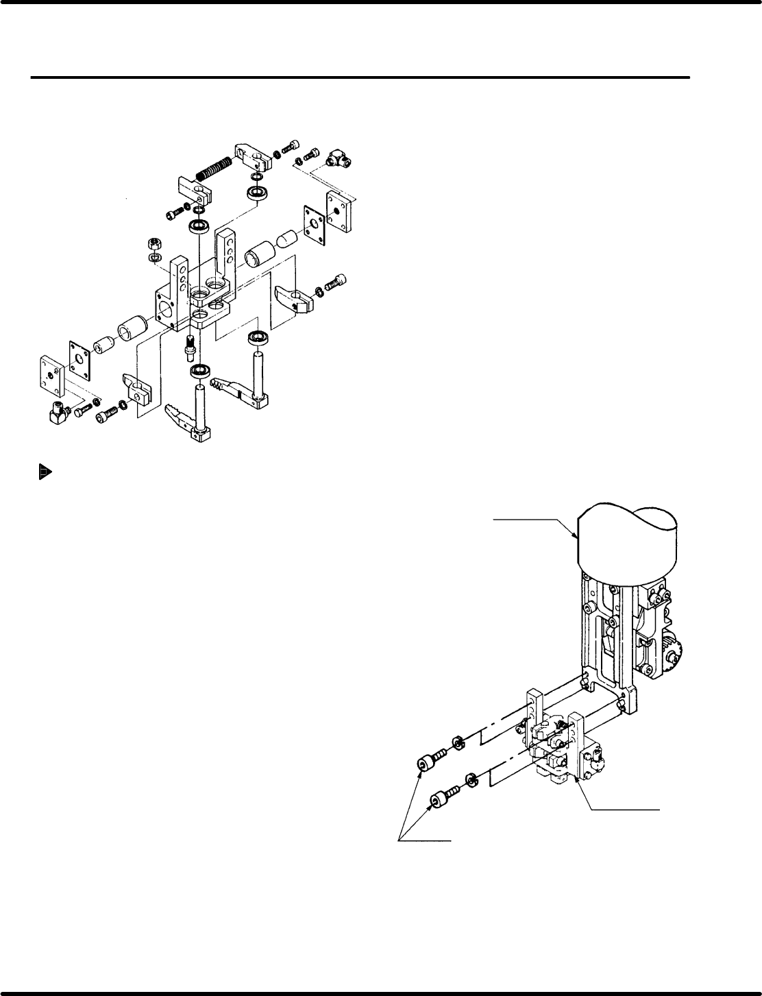
Insertion head
Guide chuck
Bolt A
5.5 Insertion Head Guide Parallelism Check and Adjustment
SERVICE MANUAL
RH5
5.5−1
DA3SEC−83−8M0−A0
5.5 Insertion Head Guide Parallelism Check and
Adjustment
DA3SEC−83−8M0−A0
Sentence No.
When to perform
x When the guide pin does not readily slip
inside the guide chuck.
x When insertion errors occur frequently.
x Allen wrench
x Box wrench
x Lever−operated dial gauge
Required tools
Guide chuck removal
1. With power to the machine OFF, loosen bolt
A (x 4) and remove the guide chuck.
2. Turn the power ON and engages the
manual mode. Then, activate the HEAD
SWIVEL LOCK.
3. Turn the hand wheel until the cam axis is
approximately at the 100q position on the
digital sequence timer.
RH5
5.5 Insertion Head Guide Parallelism Check and Adjustment
SERVICE MANUAL
5.5−2
DA3SEC−83−8M0−A0
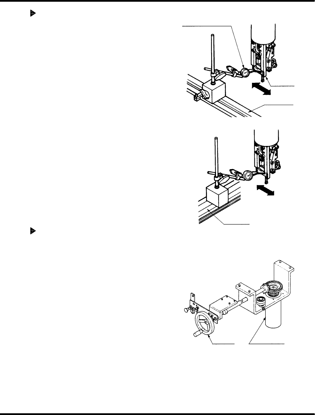
Parallelism check (Y direction)
1. Set the camshaft to 210q on the digital
sequence timer.
2. Attache the lever−operated dial gauge to
the guide rail (fixed side) on the X−Y table.
3. Set the measuring needle on the installation
surface of the guide chuck frame and bring
the scale reading to “0” (reference point).
4. Move the X−Y table in the X direction by
hand.
=CHECK=
If sliding the X− Y table by hand, make
sure the table does not slip in the Y
direction.
5. Check parallelism of the guide chuck
installation surface against the guide rail is
within 0.04/20 − 30 mm.
Parallelism check (X direction)
1. Engages the manual mode and deactivate
the HEAD SWIVEL LOCK. Then, turn the
hand wheel again until the cam shaft is
approximately at the 210q position on the
digital sequence timer. Set the measuring
needle to the installation surface of the
guide chuck frame and adjust it with 0
(reference) position on the scale.
2. Move the X−Y table in the Y direction.
=CHECK=
If sliding the X− Y table by hand, make
sure the table does not slip in the X
direction.
3. Check parallelism of the guide chuck
installation surface against the guide rail is
within 0.04/20 − 30 mm.
Lever−operated dial
gauge
Guide rail
(fixed side)
Guide chuck
(installation
surface)
Y direction
Guide rail
(fixed side)
Y direction
Head wheel
Main drive unit
Parallelism: 0.05/20 − 30
mm