Q170226E01.pdf - 第163页
RH5 5.19 Anvil Parallelism Check and Adjustment SERVICE MANUAL 5.19−2 DA3SEC−83−9BO−A0 Measuring parallelism (During insertion in the Y direction) 1. T urn ON Y INSERT on the sub−control panel and set the digital sequenc…
5.19 Anvil Parallelism Check and Adjustment
SERVICE MANUAL
RH5
5.19−1
DA3SEC−83−9BO−A0
5.19 Anvil Parallelism Check and Adjustment
DA3SEC−83−9BO−A0
Sentence No.
When to perform
x When the guide pin gets caught on the insertion
hole.
x When leads are clinched or bent unevenly.
x Lever−operated dial gauge
x Allen wrench
Required tools
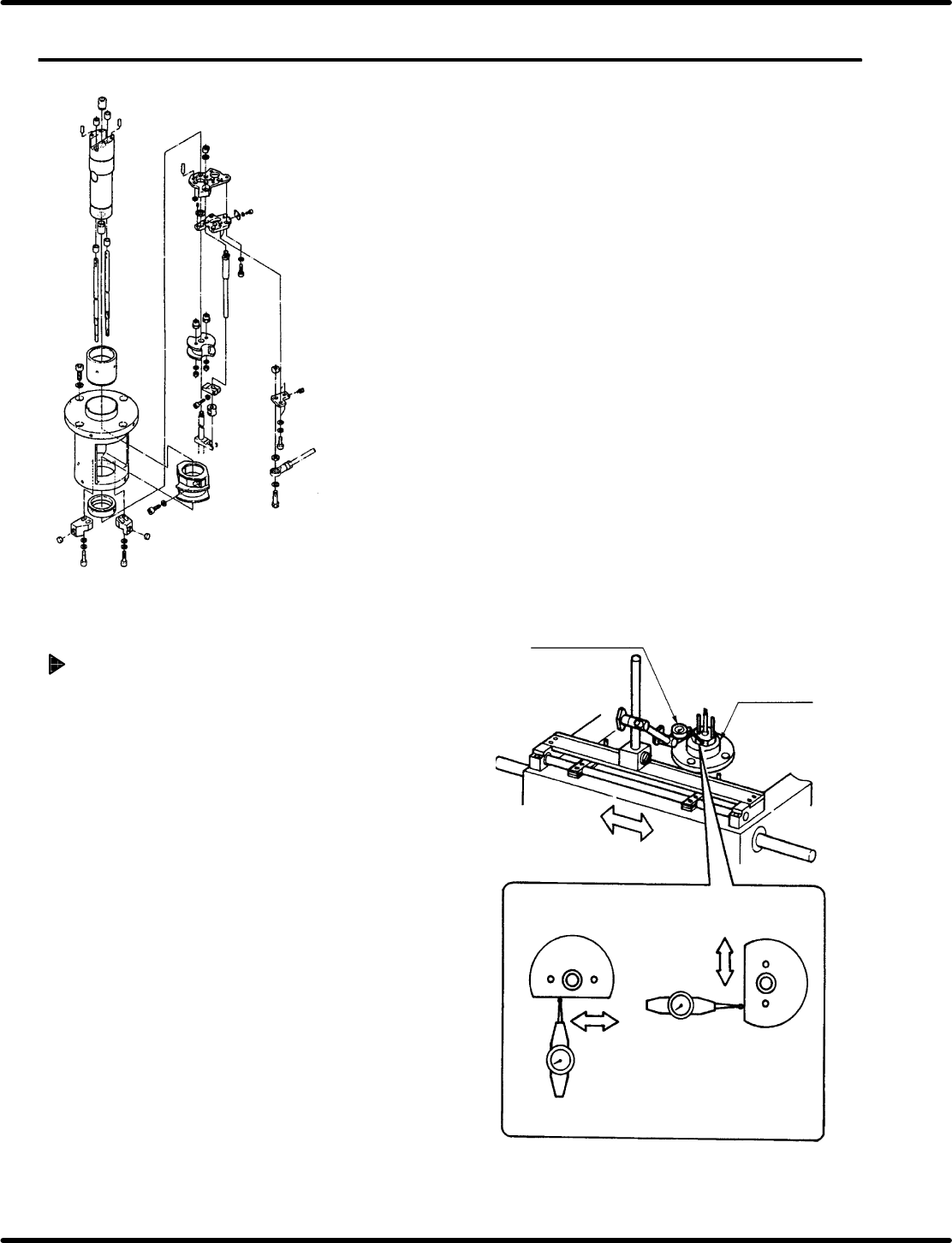
Measuring parallelism (During
insertion in the X direction)
1. T urn the hand wheel until the cam shaft is
approximately at the 210q position on the digital
sequence timer .
2. Attach the lever−operated dial gauge to the guide
rail (fixed side) on the X−Y table. Set the
measuring needle on the side surface (flat
surface) of the anvil dust cover .
3. Move the X−Y table in the X direction by hand and
check the parallelism is between 0.05/25−30 mm.
=REFERENCE=
If sliding the X− Y table by hand, make sure
the table does not slip in the Y direction.
Lever−operated dial
gauge
Dust cover
(Insertion in the
Y direction)
(Insertion in the
X direction)
Parallelism:
0.05/25 − 30 mm
RH5
5.19 Anvil Parallelism Check and Adjustment
SERVICE MANUAL
5.19−2
DA3SEC−83−9BO−A0
Measuring parallelism (During insertion
in the Y direction)
1. T urn ON Y INSERT on the sub−control panel and set
the digital sequence timer to 210q. Then fit the
measuring needle to the dust cover .
2. Move the X−Y table in the Y direction by hand and
check parallelism is between 0.05/25−30 mm.
=REFERENCE=
If sliding the X− Y table by hand, make sure the
table does not slip in the X direction.
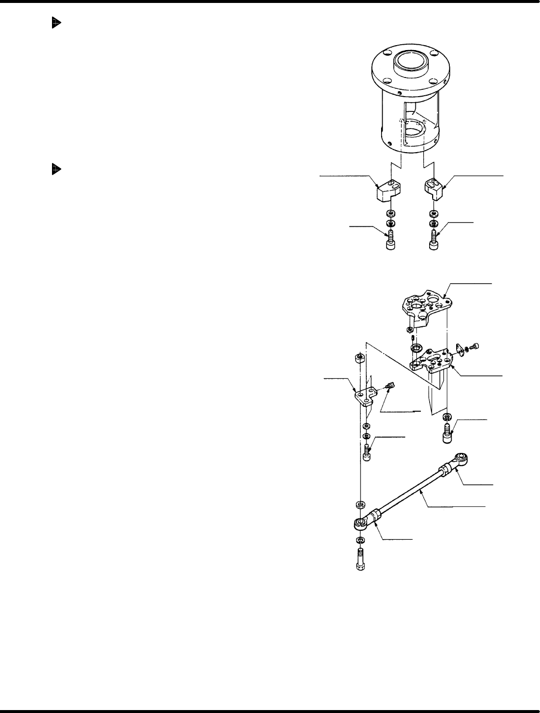
Connecting rod adjustment
1. Loosen bolts A and B (2 each) and disengage the
anvil rotation stoppers (X) and (Y).
2. Check the accuracy is at 210q in both X and Y
directions on the digital sequence timer.
=REFERENCE=
x If the ratio is not obtained, disengage the nuts
A and B of the connecting rod and adjust the
length.
x This adjustment is required only when
exchanging the rod end and connecting rod.
To adjust the accuracy only, skip these steps.
Anvil rotation
stopper (X)
Anvil rotation
stopper (Y)
Bolt B
Bolt A
Stage (3)
Stage (4)
Slider
Adjusting
screw
Bolt C
Nut B
Bolt D
Connecting rod
Nut A
5.19 Anvil Parallelism Check and Adjustment
SERVICE MANUAL
RH5
5.19−3
DA3SEC−83−9BO−A0
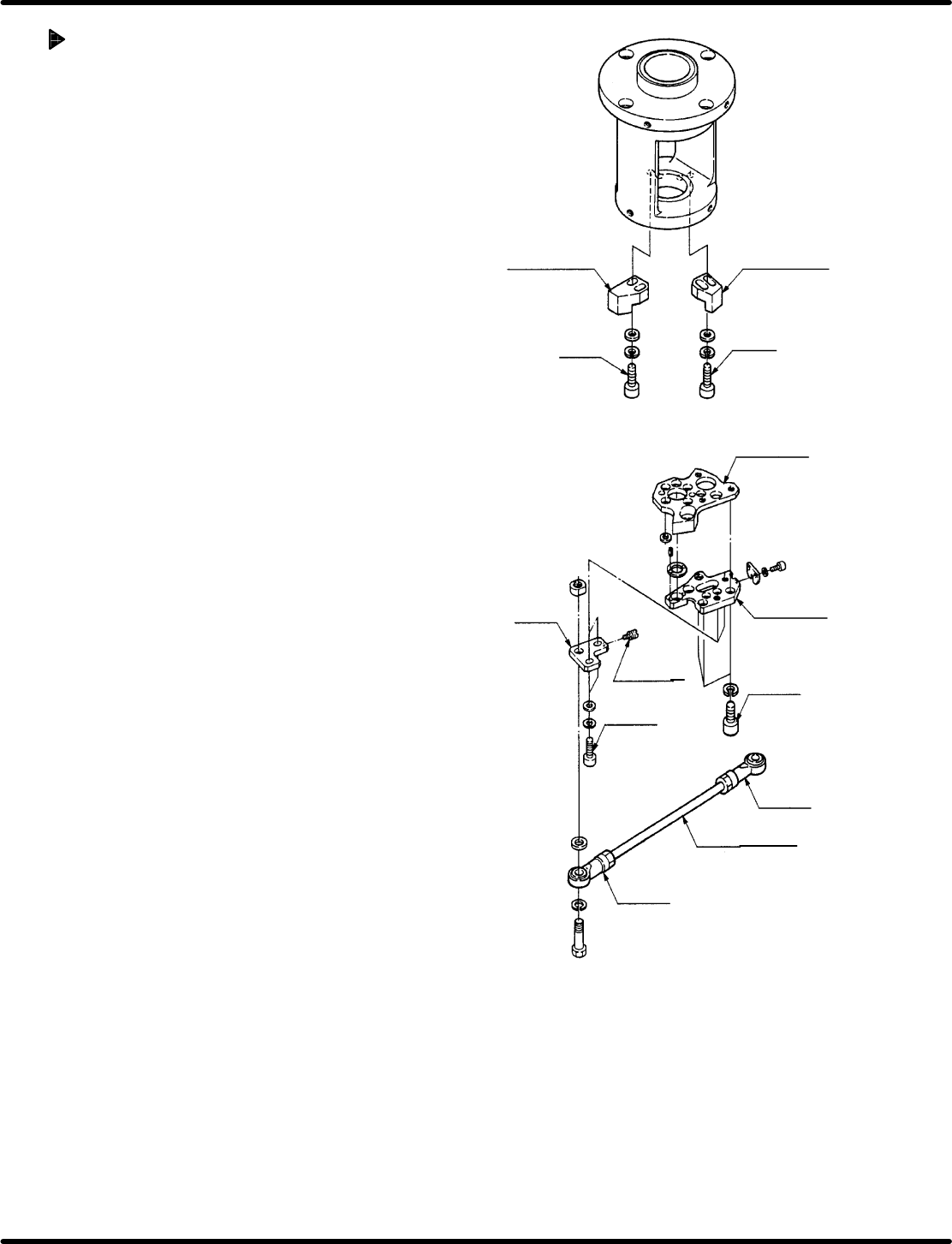
Adjusting parallelism (1)
1. Check the swing accuracy at 210q in both X
and Y directions on the digital sequence
timer.
2. If both swing accuracies are not at right
angle (90q), disengage the bolt D (x 2) and
adjust the accuracies using the adjusting
screw. (It is not necessary to measure the
exact value. Set to right angle visually.)
Example:
x If the swing exceeds by 0.6 mm in X
direction, adjust the swing not to
exceed by 0.6 mm in Y direction to set
a high angle.
x If the swing is below 1.5 mm in X
direction, adjust the swing to exceed by
1.5 mm in Y direction to set a right
angle.
3. Secure the bolt D (x 2).
4. Loosen the bolt C (x 3) of the stage (4) and
adjust the 210q swing (X direction) to be 0.
(Adjust the swing to be within 0.04 mm while
lightly tapping the stage (4) with the copper
rod.)
5. Retighten the bolt C (x 3) of the stage (4).
6. Use the hand wheel,to set the digital
sequence timer to 210q (Y direction).
(Make sure the accuracy in Y direction is
within 0.04 mm.)
=REFERENCE=
If the accuracy is not obtained within the
given range, repeat steps 1 through 6.
Anvil rotation
stopper (X)
Anvil rotation
stopper (Y)
Bolt B
Bolt A
Stage (3)
Stage (4)
Slider
Adjusting
screw
Bolt C
Nut B
Bolt D
Connecting rod
Nut A