Q170226E01.pdf - 第274页
7.2 AC Servomotor Adjustment SERVICE MANUAL RH5 7.2−19 DA3SEC−84−300−A0 User Constant Cn−01 (Memory Switch) List Selected item Bit No. De− fault Description Reference Sequence input 0 0 Turns ON/OFF servo via external in…
RH5
7.2 AC Servomotor Adjustment
SERVICE MANUAL
7.2−18
DA3SEC−84−300−A0
7.2.5 Setting/Browsing User Constant (Memory Switch)
(Cn−01 and Cn−02)
User constants Cn−01 and Cn−02 can be set or browsed by bits as a memory switch.
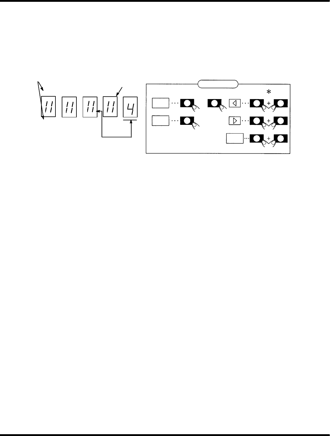
Figure 7.2−1 shows the functions of switches after the bit data is displayed.
To change Cn−01 or Cn−02 (User constants), turn ON the control power to enable the preset functions.
Panel display
EC A B6 42 0
FD B 97 53 1
SW2 SW1 SW3
SW4 SW1 SW3
SW1 SW3
DATA
bit
SET
Bit No.
Light up when ON
bit No. to be set
* Show that SW2 (SW3 or SW4) shall be pressed
while holding SW1 down.
or
Switch function
Figure 7.2−1− Function Switches
1. Using the arrow keys, set the bit No. of the memory switch to be set to the right end of the panel.
2. Using “bit” key, turn ON/OFF the memory switch. (Either SW2 or SW3 is permissible.)
(The lamp lights up when ON and goes out when OFF.)
3. Repeat steps 1 and 2 as necessary.
4. Press “SET” to store data.
5. Press “DATA” to return to the screen.
6. Press “SET” to switch to the monitor mode.
Here following describes the functions of the memory switches of the user constants Cn−01 and Cn−02.

7.2 AC Servomotor Adjustment
SERVICE MANUAL
RH5
7.2−19
DA3SEC−84−300−A0
User Constant Cn−01 (Memory Switch) List
Selected
item
Bit No. De−
fault
Description Reference
Sequence input 0 0 Turns ON/OFF servo via external input (SV−ON) 0
1 Normally being ON.
1
SR
BY
l
0 Uses external input (SEN). 0
SR BY only
1 Regards the AC motor as high speed automatically inside
the servo pack regardless of whether SEN signal is input
or not.
2 0 Disables driving in normal rotation via P−OT signal. 0
1 Enables driving in normal rotation normally.
3 0 Disables driving in reverse rotation via N−OT signal. 0
1 Enables driving in reverse rotation normally.
Input signal 4 0 Uses IN−A input. 0
1 Regards IN−A as “0” inside the sevo pack regardless of
whether IN−A signal is input or not.
5 0 Uses IN−B input. 0
1 Regards IN−B as “0” inside the sevo pack regardless of
whether IN−B signal is input or not.
Abnormal stop 6 0 <DB stop>
Applies the dynamic brake to stop the motor.
0
1 <Free run stop>
Stops the motor in free running mode.
7 0 <DB OFF after applying DB>
Releases the dynamic brake even after the motor has
stopped.
0
1 <DB ON after applying DB>
Applies the dynamic brake even after the motor has
stopped.
8 0 Follow the same procedure as in bit No. 6 for stopping
during overtraveling.
0
1 <Zero speed stop during overtraveling>
Apply the motor to stop with the torque set in the user
constant Cn−06 during overtraveling.
9 0 BB is applied after zero stop during overtraveling 0
1 Performs zero clamp after zero stop during overtraveling.

RH5
7.2 AC Servomotor Adjustment
SERVICE MANUAL
7.2−20
DA3SEC−84−300−A0
Selected
item
Bit No. De−
fault
Description Reference
Mode switch (Only
speed control)
D/C 0/0 <Torque command>
It can be activated when the set torque vale is conformed
to user constant Cn−0C.
0/1 <Speed command>
It can be activated when the set value is conformed to
user constant Cn−0C.
00
1/0 <Acceleration>
It can be activated when the set value is conformed to
user constant Cn−0E.
1/1 Mode switch function not supported
External brake E 0 No brake command function 0
1 Brake command function supported
Overload alarm F 0 No overload alarm function 0
1 Overload alarm function supported
=REFERENCE=
x Bit No. 8: Follow the same procedure as in bit No. 6 for abnormal stopping when controlling the
torque.
x Bit No.09: Selects 0 or 1 after completing zero speed stop is selected.
x Bit No. C/D: Selects the conditions for activating the mode switch.
When the mode switch activates, the speed control will be switched to P control. This
is, however, available only for controlling the speed.