Q170226E01.pdf - 第190页
5.29 Checking and Replacing Main Drive Unit and T op/Bottom Timing SERVICE MANUAL RH5 5.29−1 DA3SEC−83−9M0−A0 5.29 Checking and Replacing Main Drive Unit and T op/Bottom Timing DA3SEC−83−9M0−A0 Sentence No. Timing check …
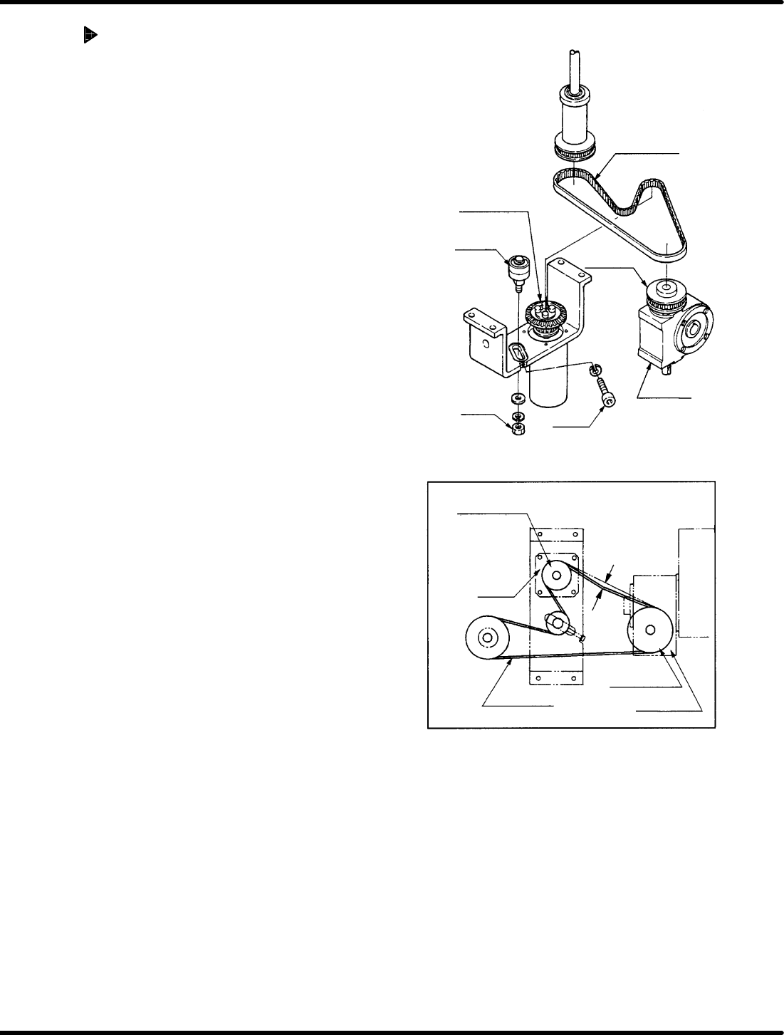
Timing belt
Timing pulley
(motor side)
Reduction gear
Bolt A
Bearing
Nut A
Timing pulley
(motor side)
Reduction gear
Timing pulley
Motor
Timing belt
Deflection of
5 − 10 mm
Timing
pulley
RH5
5.28 Main Drive Unit Timing Belt Replacement and Adjustment
SERVICE MANUAL
5.28−2
DA3SEC−83−9L0−A0
Adjusting belt tension
1. Tighten the nut A temporarily and the
adjust the tension of the timing belt with
bolt A.
2. Check the belt gives 5 to 10 mm when
pressed on. If outside this range, make
readjustments with the bolt A.
3. Tighten the nut A.
5.29 Checking and Replacing Main Drive Unit and Top/Bottom Timing
SERVICE MANUAL
RH5
5.29−1
DA3SEC−83−9M0−A0
5.29 Checking and Replacing Main Drive Unit and
Top/Bottom Timing
DA3SEC−83−9M0−A0
Sentence No.
Timing check
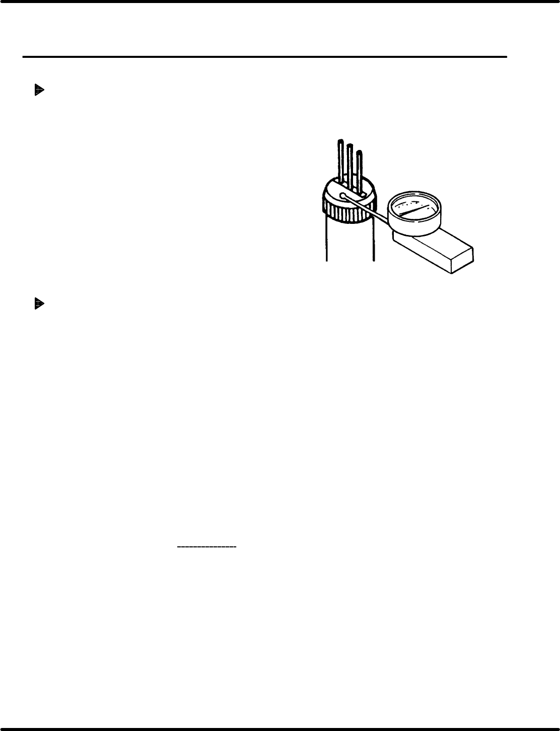
1. Remove the guide chuck and anvil unit.
2. Turn the hand wheel to set the guide pin to the
uppermost position and insert the measuring
needle of the dial gauge into the cartridge.
3. Turn the hand wheel slowly in the clockwise
direction to secure it where the measuring
needle of the dial gauge moves by 0.01 mm.
4. Press “F6” (SEQ TIMER) on the main control
panel to display the angle.
5. Check that the current angle indicates 230q.
Timing adjustment
1. Set the mode to “SEMI” − “1BLOCK” −
”MANU” − “1BLOCK” on the main control
panel.
=REFERENCE=
This will reset the monitor screen.
2. Press “REQ” − “F6” − “F1” − “F2” − “F6”
in order.
3. Set the digital sequence timer to “RESET
mode”.
4. Set the mode to “SEMI” − “1BLOCK” −
”MANU” − “1BLOCK” on the main control
panel and press “F6” (SEQ TIMER).
5. Repeat steps 1 through 5 in “Timing check
”
above.
Ex.: When the guide pin starts lowering at
300q in timing.
6. Since the cam timing is delayed by 70q, turn
the hand wheel to set the digital sequence
timer to 70q .
7. Press “F1” (CH) − “0” − “F2” (SET) −
“F5” (T) − “F2” (SET) in order.
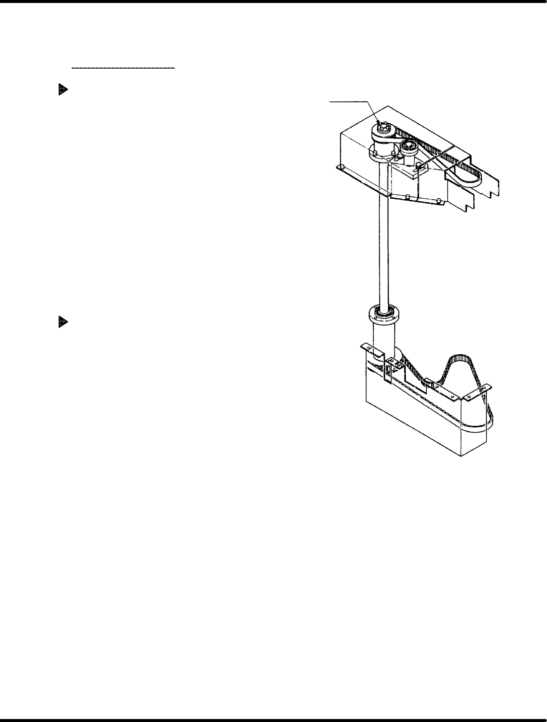
ETP bush
RH5
5.29 Checking and Replacing Main Drive Unit and Top/Bottom Timing
SERVICE MANUAL
5.29−2
DA3SEC−83−9M0−A0
=REFERENCE=
The reading on the digital sequence
timer changes from 70q to 0q.
8. Check the timing
again.
Top and bottom timing check
1. Turn the hand wheel to lower the insertion
pusher and get a stable position. Then insert
the measuring needle into the insertion
pusher.
2. Turn the hand wheel slowly in the clockwise
direction to secure it where the measuring
needle of the dial gauge moves by 0.01
mm.
3. Press “F6” (SEQ TIMER) on the main
control panel to display the angle.
4. Make sure that the angle indicates 230 r1q.
Top and bottom timing adjustment
Ex.: When the guide pin lowers at 230q in
timing and the insertion pusher lowers
at 240q in timing
1. Turn the hand wheel to set the digital
sequence timer to 0q.
2. Disengage the ETP bush at the upper base
of the drive unit.
=REFERENCE=
Disengaging the ETP bush releases the
top and bottom driving.
3. Set the digital sequence timer to 10q by
turning the hand wheel in the clockwise
direction.
=CHECK=
Turn the hand wheel while holding the
pulley of the power axis not to move the
upper cam box.
4. Fix the ETP bush at the upper base of the
drive unit.
5. Check/adjust all the above mentioned
timings and make sure that the lowering
timing of the guide pin and insertion
chuck is 230 q.