Q170226E01.pdf - 第145页
RH5 5.14 Insertion Head Insertion Chuck Claws/Rubber Replacement/Adjustment SERVICE MANUAL 5.14−2 DA3SEC−83−8WO−A0 Chuck rubber replacement 1. Remove the rubber from the chuck claw . =REFERENCE= The rubber pops out easil…
5.14 Insertion Head Insertion Chuck Claws/Rubber Replacement/Adjustment
SERVICE MANUAL
RH5
5.14−1
DA3SEC−83−8WO−A0
5.14 Insertion Head Insertion Chuck Claws/Rubber
Replacement/Adjustment
DA3SEC−83−8WO−A0
Sentence No.
When to perform
x When inserted parts are often slanted.
x When insertion errors occur frequently.
Required tools
x Allen wrench
x Box wrench
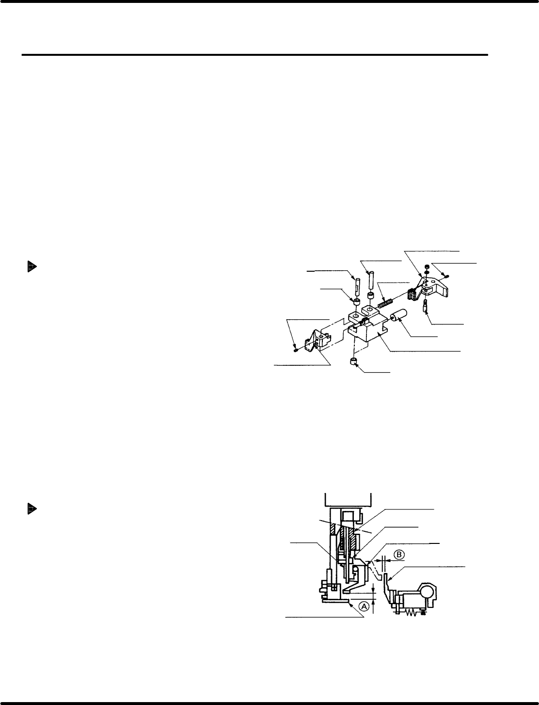
Chuck claw replacement
1. Remove set screws C and D (2 each).
2. Remove the fulcrum pin.
3. Remove the compression spring.
4. Remove the connection pin.
5. Replace the old claws with new ones, and
assemble those parts following the above
procedure in reverse.
=REFERENCE=
Check and adjust the accuracy of M6
insertion head, insertion chuck 100q
swing. (Refer to ‘5.6 Insertion Head
Insertion Chuck Parallelism Check and
Adjustment’.)
Adjusting chuck claws
1. Bring the insertion head to point (A).
Reposition the stopper so that the bottom
surface of the insertion chuck and the top
surface of the lead guide chuck claws are
level with one another.
2. Bring the transfer chuck to point (B).
Reposition the stopper so that the bottom
surface of the insertion chuck and the top
surface of the transfer chuck claws are level
with one another.
Chuck claw (C)
Set screw C
Connecting
pin
Piston
Insertion chuck body
Push
Push
Fulcrum pin
Fulcrum pin
Set screw D
Chuck claw (D)
Compression
spring
Insertion head
Stopper
Insertion chuck
Transfer chuck
Pusher
Lead guide chuck
RH5
5.14 Insertion Head Insertion Chuck Claws/Rubber Replacement/Adjustment
SERVICE MANUAL
5.14−2
DA3SEC−83−8WO−A0
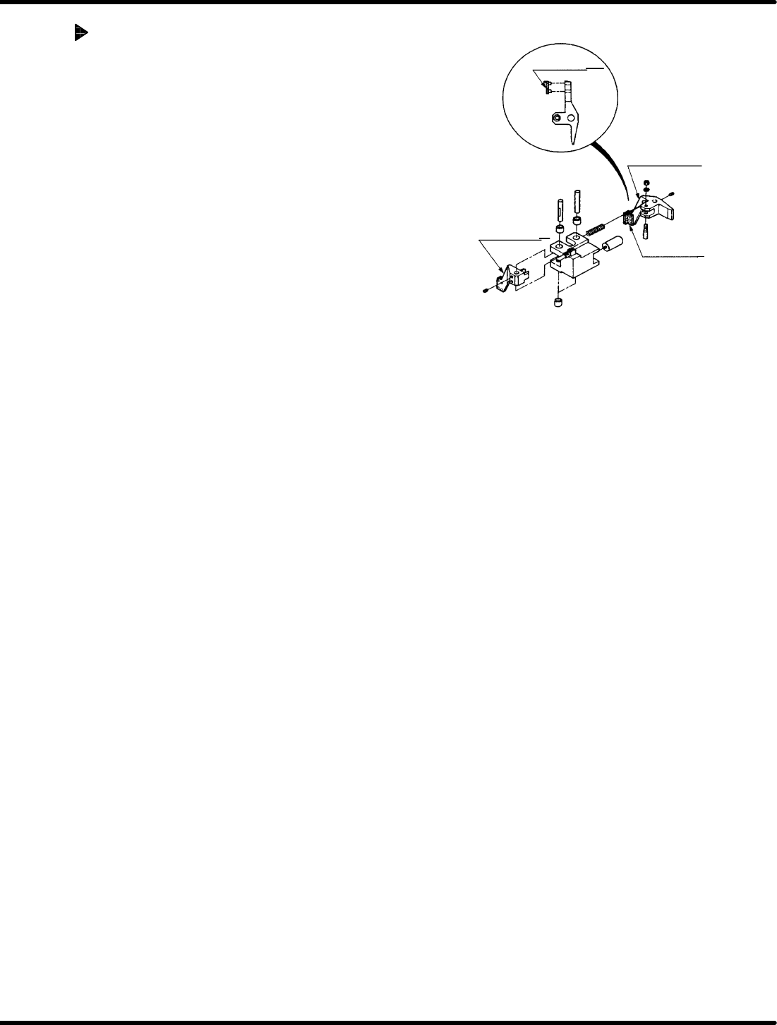
Chuck rubber replacement
1. Remove the rubber from the chuck claw.
=REFERENCE=
The rubber pops out easily.
2. Attach a new rubber.
Chuck rubber
Chuck claw (D)
Chuck claw (C)
Chuck rubber
5.15 Lead Cutter and Tape Cutter Replacement and Adjustment
SERVICE MANUAL
RH5
5.15−1
DA3SEC−83−8XO−A0
5.15 Lead Cutter and Tape Cutter Replacement and
Adjustment
DA3SEC−83−8XO−A0
Sentence No.
When to perform
x When cutting errors occur frequently
due to worn or damaged cutter
blades.
x When insertion errors occur
frequently.
x Allen wrench
x Gap gauge
Required tools
Preparations
x Move the parts feeder to a position from
which it is easier to remove the cutter blade
from the rear of the machine.
x Detach the parts detection bracket.
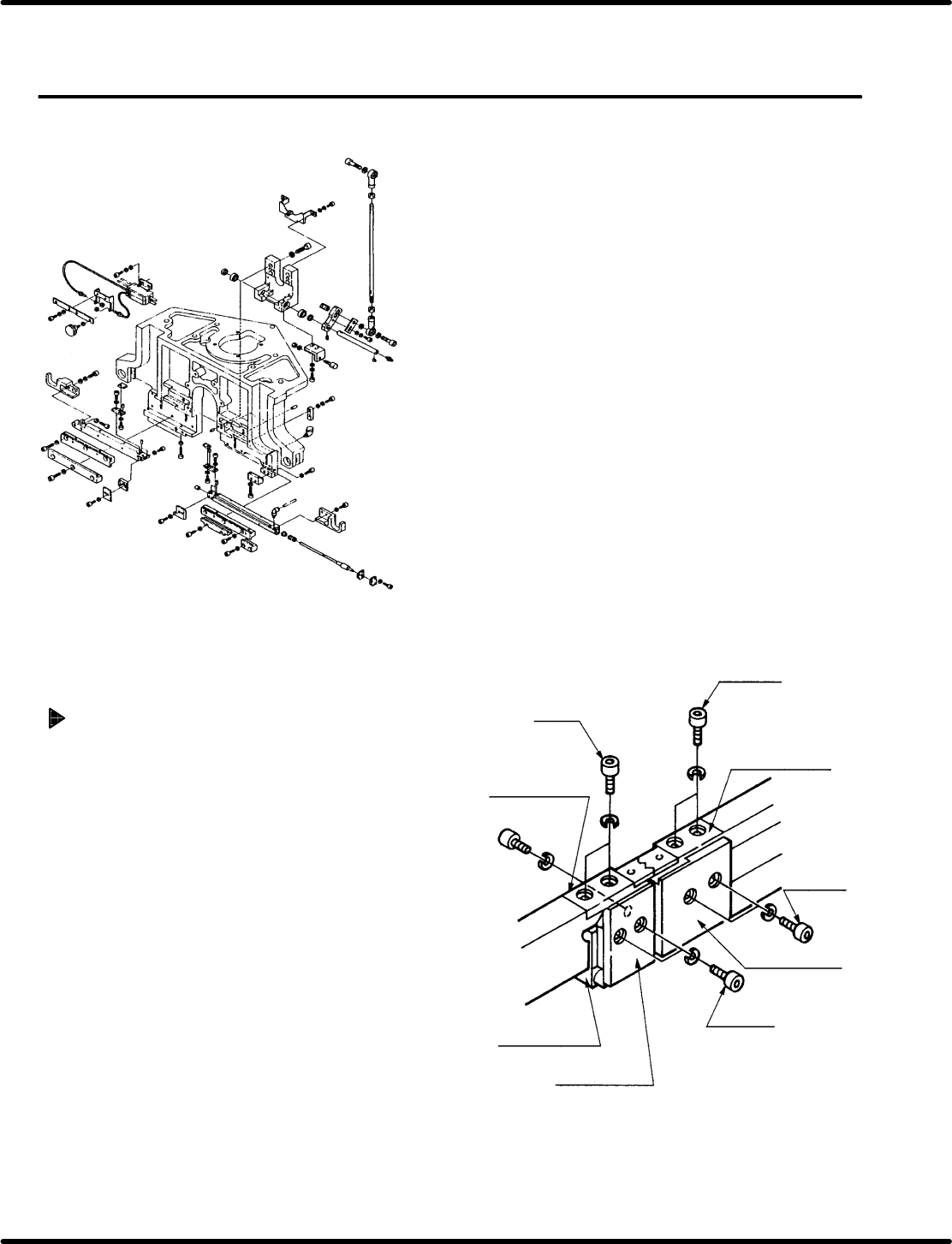
Lead cutter and tape cutter removal
1. Remove bolts A1 and B1 (2 each) fixing lead
cutters (A) and (B).
2. Remove bolts A1 and B1 (2 each) fixing lead
cutters (A) and (B).
Bolt B1
Bolt A1
Lead cutter (B)
Lead cutter (A)
Bolt B2
Bolt A2
Tape cutter B2
Tape cutter (A)
Cutter body block