Q170226E01.pdf - 第159页
RH5 5.17 Anvil Insertion Detection Amplifier Check SERVICE MANUAL 5.17−4 DA3SEC−83−8ZO−A0 = MEMO =
5.17 Anvil Insertion Detection Amplifier Check
SERVICE MANUAL
RH5
5.17−3
DA3SEC−83−8ZO−A0
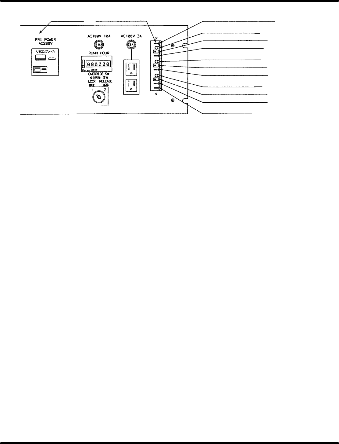
Figure 5.17−3− Distortion gauge amplifier board volume and check pin assignments
Power source
unit
Distortion gauge
amplifier board
TPC: comparator voltage check pin
LED1: Ch1 output monitor
VR1: Ch1 sensitivity control
TP1: Ch1 voltage check pin
LED2: Ch2 output monitor
VR2: Ch2 sensitivity control
TP2: Ch2 voltage check pin
LED3: Ch3 output monitor
VR3: Ch3 sensitivity control
TP3: Ch3 voltage check pin
TPGND: Grand pin

RH5
5.17 Anvil Insertion Detection Amplifier Check
SERVICE MANUAL
5.17−4
DA3SEC−83−8ZO−A0
= MEMO =
5.18 Anvil Cutter Blade Replacement and Adjustment
SERVICE MANUAL
RH5
5.18−1
DA3SEC−83−9AO−A0
5.18 Anvil Cutter Blade Replacement and Adjustment
DA3SEC−83−9AO−A0
Sentence No.
When to perform
x When parts leads are not cut.
x When part leads are bent after being cut.
x When insertion errors occur frequently.
x Allen wrench
x Gap gauge
Required tools
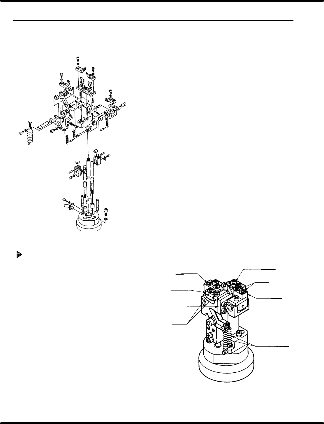
Fixed blade replacement
1. Remove bolt A (x 4) securing the fixed blades in
place.
2. Insert new blades being careful to install them
in the proper places, and fix them in place with
bolt A (x 4).
=REFERENCE=
There are two types of fixed blades.
Be sure to install the blades in the proper
places.
Moving blade A
Bolt A
Fixed blade
Spring for cut
& clinch lever
Fixed blade
Moving
blade A
Moving
blade B
Bolt A