Q170226E01.pdf - 第240页
RH5 6.1 Checking Maintenance Precision SERVICE MANUAL 6.1−3 DA3SEC−89−010−A0 No. Check item Description Illustration Criteria Measured value 10 Pickup test Insertion pusher parallelism T o be measured at 295 Bolt Measu…
6.1 Checking Maintenance Precision
SERVICE MANUAL
RH5
6.1−2
DA3SEC−89−010−A0
No.
Check item
Description
Illustration
Criteria
Measured
value
5
6
7
8
9
Bolt
M6 x 2
M8 x 4
OK/NG
0to0.40mm
White marker
check
mm
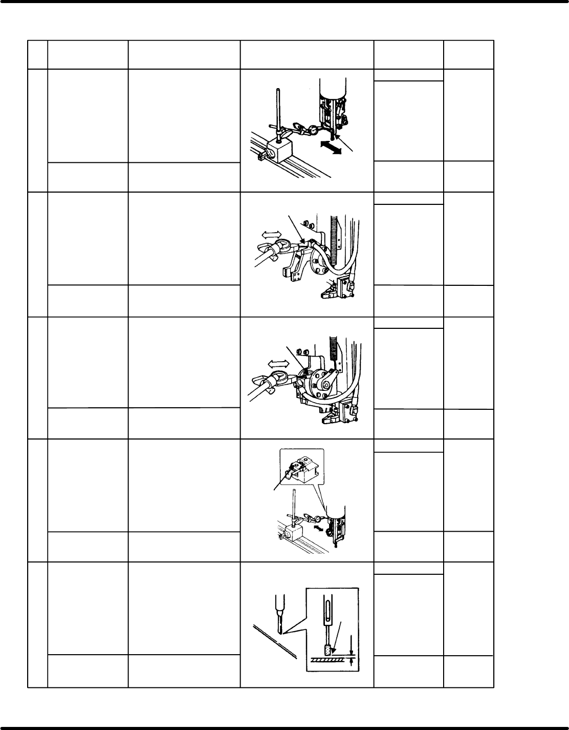
Pickup test
Insertion head
swing precision
(Y direction)
To be measured at
210
Bolt
Insertion chuck
parallelism
To be measured at
0
M4 x 2
Measure the swing precision
of the guide chuck installation
surface by moving the table
in X direction.
Measure the value within the
range of 50 mm
(Measure the value with the
Y lock unit engaged.)
Measure the parallelism
when the insertion chuck is
at the transfer position by
moving the table.
Measure the value within the
range of 25 mm.
mm
mm
mm
mm
0to0.03mm
0to0.03mm
0to0.03mm
0to0.5mm
Thickness gauge
Bolt
M4 x 2
Insertion chuck
perpendicularity
To be measured at
210
Measure the perpendicularity
when the insertion chuck is
angled at 210 by moving the
table.
Measure the value within the
range of 25 mm.
Measurement
surface
Measurement
surface
Measurement
surface
Measurement
surface
Pickup test
Pickup test
Pickup test
White marker
check
White marker
check
White marker
check
White marker
check
Bolt
M6 x 1
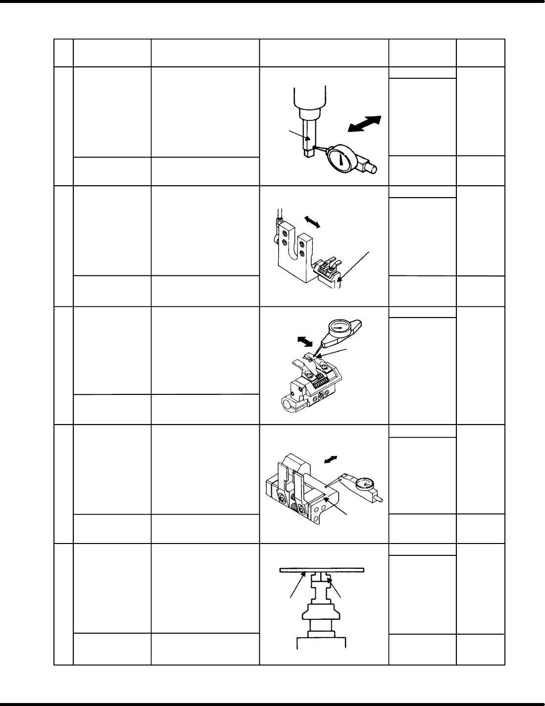
Insertion chuck axis
perpendicularity
To be measured at
210
Measure the perpendicularity
when the insertion chuck is
angled at 210 by moving the
table in Y direction.
Measure the value within the
range of 25 mm.
OK/NG
OK/NG
OK/NG
OK/NGM4 x 2
Bolt
Insertion pusher
height precision
Measure the clearance
between the end of the
pusher and the top surface of
the PC board when the
insertion pusher is at the
lowermost point.
Clearance
RH5
6.1 Checking Maintenance Precision
SERVICE MANUAL
6.1−3
DA3SEC−89−010−A0
No.
Check item
Description
Illustration
Criteria
Measured
value
10
Pickup test
Insertion pusher
parallelism
To be measured at
295
Bolt
Measure the flat surface at
the origin position.
Measure the value within
the range of 5 mm.
* Perform slide check.
M4 x 1
11
12
13
14
0to0.03mm
0to0.04mm
Bolt
OK/NG
0to0.05mm
White marker
check
mm
Pickup test
Measure the installation
precision by moving the
transfer chuck manually to
make sure that there is no
play in axial direction.
mm
M4 x 3
At 0:
mm
At 270:
mm
0to0.04mm
−0.05to0.05mm
mm
mm
Measurement
surface
Pickup test
White marker
check
OK/NG
White marker
check
White marker
check
OK/NG
OK/NG
Bolt
M4 x 3
M5 x 2
M8 x 4
Bolt
M5 x 2
Bolt
M6 x 2
Transfer chuck
installation
precision in axial
direction
Transfer chuck
parallelism
To be measured at
260
To be checked at 0
No play in Y
direction
With the transfer chuck at the
chucking position, measure
the parallelism at the top
surface of the claw (left side)
by moving the XY table by 20
mm in Y direction.
Measuring
surface
Measuring
surface
Transfer chuck
perpendicularity
To be measured at
90
With the transfer chuck at the
transfer position, measure
the perpendicularity at the
surface of of the chuck body
by moving the XY table by 20
mm in Y direction.
Anvil height
precision
To be measured at
275
Measure the height of the
anvil uppermost position by
using the PCB transfer
surface of the XY table as the
reference. (Center of the
fixed block)
PC board
Uppermost
position
Pickup test
Pickup test
6.1 Checking Maintenance Precision
SERVICE MANUAL
RH5
6.1−4
DA3SEC−89−010−A0
No.
Check item
Description
Illustration
Criteria
Measured
value
15
Bolt
M5 x 3
M6 x 4
M8 x 4
16
17
18
19
0to0.04mm
mm
0to0.04mm
0.50.1 mm
mm
mm
mm
mm
0to0.02mm
0to0.02mm
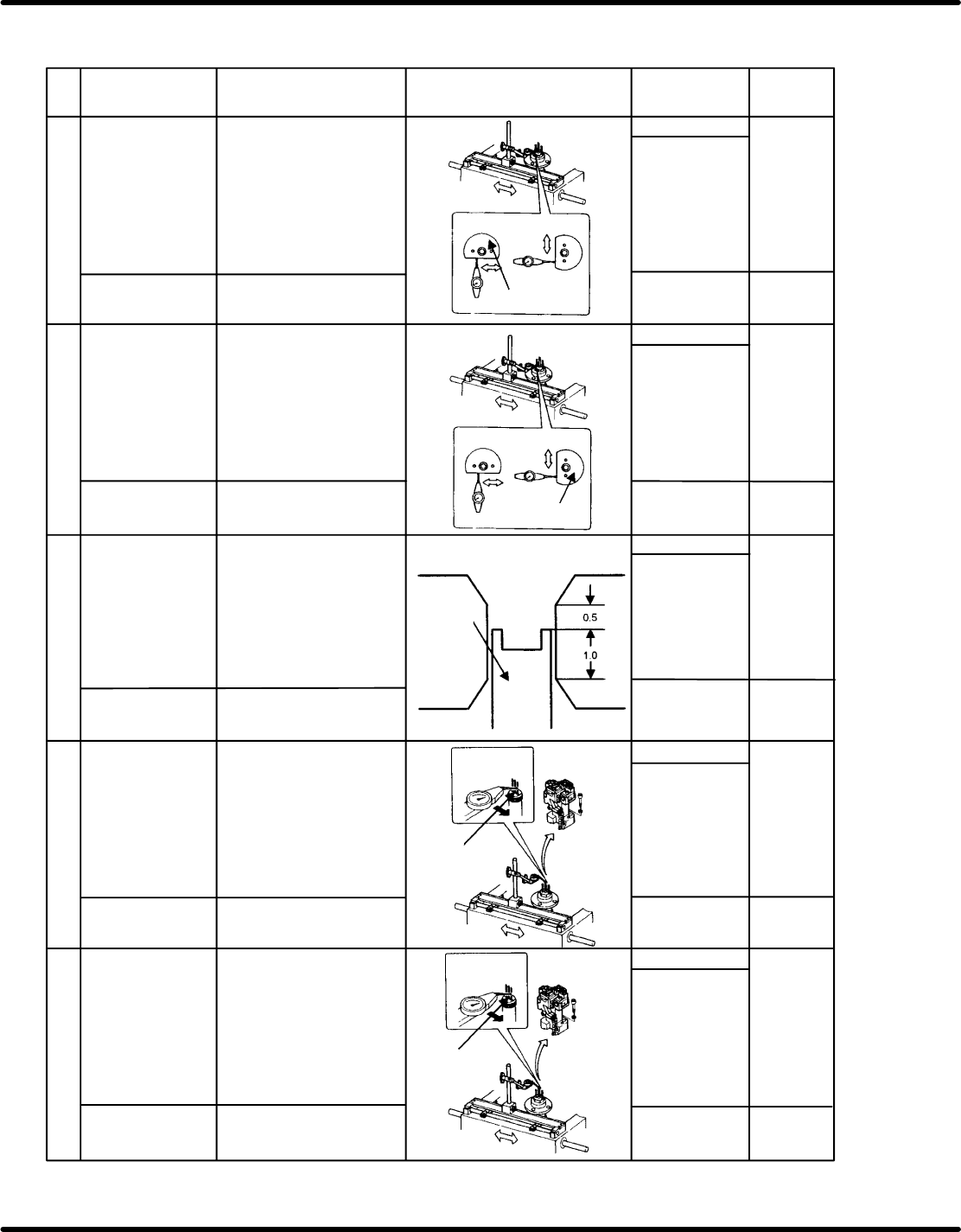
Anvil swing
precision (insertion
in X direction)
To be measured at
210
Measure the swing precision
of the anvil by moving the
measuring side of the dust
cover by 50 mm in X
direction with respect to the
XY table.
Pickup test
Pickup test
*******
Pickup test
Pickup test
OK/NG
White marker
check
OK/NG
White marker
check
OK/NG
White marker
check
OK/NG
White marker
check
OK/NG
White marker
check
Bolt
M6 x 2
M8 x 3
Bolt
M6 x 2
Bolt
M6 x 1
Bolt
M6 x 1
Anvil swing
precision (insertion
in Y direction)
To be measured at
210
In X direction
Guide pin height
precision
To be measured at
205
Ensure that the edge of the
pin is 0.5 mm below the top
end of the flat surface when
the lead guide pin is at the
uppermost position.
(Visually check with a scope.)
in Y direction
Guide pin
0.5
1.0
Guide pin swing
precision
(insertion in X
direction)
To be measured at
210
Measure the swing precision
of the guide pin by moving it
2 mm below the top surface
of the cartridge from the XY
table in X direction.
Measure the swing precision
of the anvil by moving the
measuring side of the dust
cover by 50 mm in Y
direction with respect to the
XY table.
Guide pin swing
precision
(insertion in Y
direction)
To be measured at
210
Measure the swing precision
of the guide pin by moving it
2 mm below the top surface
of the cartridge from the XY
table in Y direction.
Measuring
point
Measuring
point