Q170226E01.pdf - 第363页
RH5 8.8 Monitoring I/O Signals SERVICE MANUAL 8.8−2 DA3SEC−85−520−A0 Example 1) If the numbers (2 digits) applied for 07 of the monitoring address 70000 is A2 as shown below , the following will be revealed according to …
8.8 Monitoring I/O Signals
SERVICE MANUAL
RH5
8.8−1
DA3SEC−85−520−A0
8.8 Monitoring I/O Signals
DA3SEC−85−520−A0
Sentence No.
Procedure
1. Select “F2” (MONITORING) on the operation screen.
2. Select “F3” (MEMORY) on the monitoring screen.
3. Select “F1” (CPU).
4. Call up the I/O table and monitor the signals according to the procedures below.
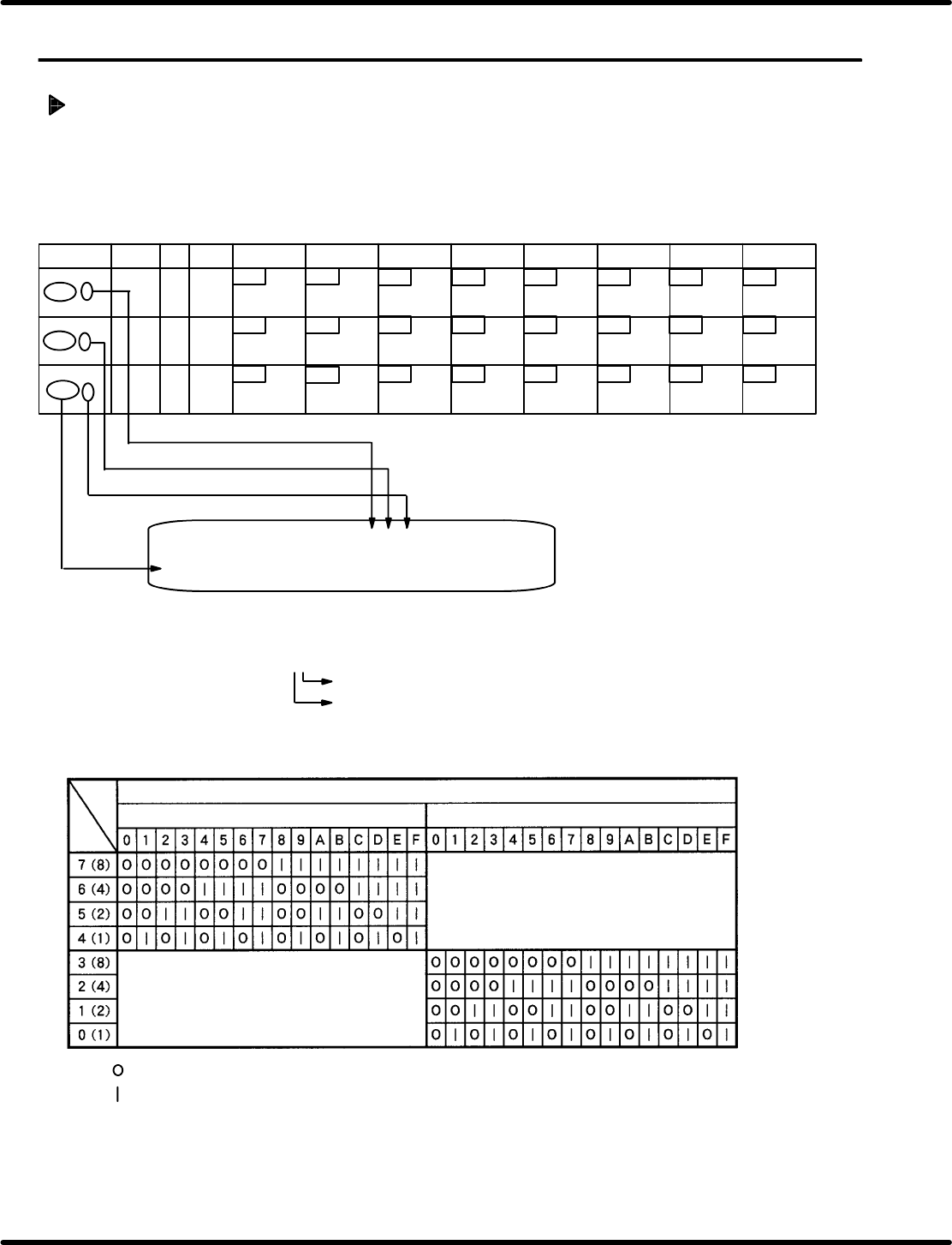
: Applied I/O signal for bit is OFF
: Applied I/O signal for bit is ON
Monitoring screen
ADDRESS CPU 00 01 02 03 04 05 06 07 08 09 0A 0B 0C 0D 0E 0F
70000 ** ** ** ** ** ** ** ** ** ** ** ** ** ** ** **
**: Numerics 0−9 or letters A −F
**
The one place: Display monitor of the lower bits (0−3)
Ten’s digits: Display monitor of the upper (4 − 7) bit.
Enter the desired address adding “0”
Ten’s digit
Numeric (**) on the monitor
The one place
Bit
Insertion
detection 4
Insertion
detection 3
Insertion
detection 2
Insertion
detection 1
67
00
66
65
64
63
62 61 60
ADDRESS
LABEL BLK
DEV
7 bit 6 bit
5 bit
4 bit
3 bit 2 bit 1 bit 0 bit
7000 6
7000 7
7000 8
77 76 75
00
0 100
Cutter return
Cutter forward
Mecha lock
return (Feed
lock rerun)
Mecha lock
forward (Feed
lock forward)
Parts exhaust
pre−detection
107
74
73 72 71
70
Upper cover
rear (Usually
ON)
Upper cover
front (Usually
ON)
Invert swivel
reverse limit
Invert swivel
forward limit
Invert unit
lower limit
Invert unit
upper limit
100
106 105 104 103
102
101
RH5
8.8 Monitoring I/O Signals
SERVICE MANUAL
8.8−2
DA3SEC−85−520−A0
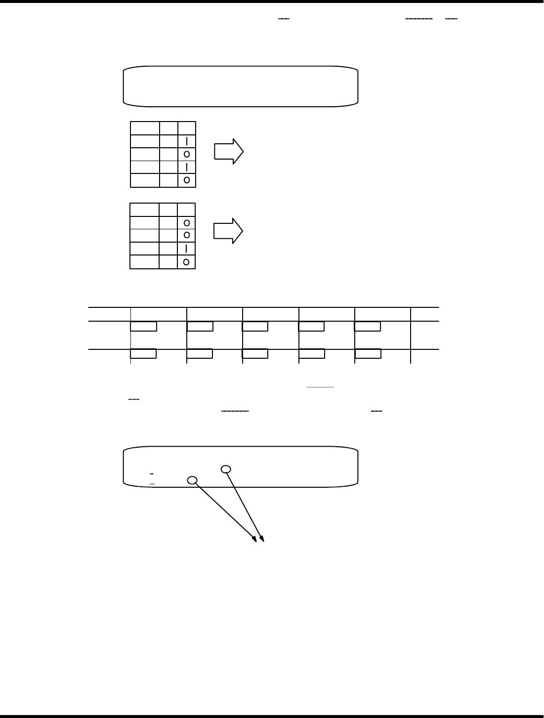
Example 1) If the numbers (2 digits) applied for 07
of the monitoring address 70000 is A2 as shown
below, the following will be revealed according to the input table and I/O status
table.
When 7 Bit is ON, cutter return signal is ON.
When 5 Bit is ON, mechanical lock return signal is ON.
Bit A
7
6
5
4
Bit 2
3
2
1
0
Monitoring screen
ADDRESS CPU 00 01 02 03 04 05 06 07 08 09 0A 0B 0C 0D 0E 0F
70000 ** ** ** ** ** ** ** A2 ** ** ** ** ** ** ** **
When 1 Bit is ON, head swivel lock return signal is ON.
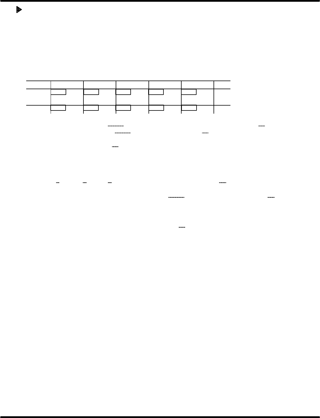
Example 2) To check whether the cut waste drop function is activated:
ADDRESS
7 bit
6 bit 5 bit 4 bit 3 bit
7004 3
37 36 35 34
33
47 46 45 44 43
Transfer chuck
OFF
Transfer chuck
ON
Cut waste drop
Insertion pusher
high pressure
Cutter
Output table − 1
From the output table, select the monitoring address 70040 to check the status of the upper bit (ten’s
digit) under 03
.
Or select the monitoring address 70043
to check the number under 00. (Same results will be
obtained.)
Monitoring screen
ADDRESS CPU 00 01 02 03 04 05 06 07 08 09 0A 0B 0C 0D 0E 0F
70040
** ** ** ** ** ** ** ** ** ** ** ** ** ** ** **
70043 ** ** ** ** ** ** ** ** ** ** ** ** ** ** ** **
In this case, when 5 bit is ON (any of 2*, 3*, 6*, 7*, A*, A*, B*, E*, F* is ON from
comparison table), cut waste drop function is activated.
Similarly, monitoring function enables you to check the status of I/O signals.
8.8 Monitoring I/O Signals
SERVICE MANUAL
RH5
8.8−3
DA3SEC−85−520−A0
Forced output (Reference)
1. Select “F2” (MONITORING) on the operation screen.
2. Select “F3” (MEMORY) on the monitoring screen.
3. Select “F1” (CPU).
4. Call up the output table to perform forced output according to the procedures below.
Example) To turn ON cut waste drop function forcibly:
ADDRESS
7 bit
6 bit 5 bit 4 bit 3 bit
7004 3
37 36 35 34
33
47 46 45 44 43
Transfer chuck
OFF
Transfer chuck
ON
Cut waste drop
Insertion pusher
high pressure
Cutter
Output table − 1
Select the monitoring address 70040 from the output table to check the the number under 03.
Or select the monitoring address 70043
to check the number under 00. (Same results will be
obtained.)
(Here, displayed number is 84
as an example.)
The number within paren ( ) of the BIT in the comparison table to be output is added to the displayed
number.
(As for cut waste drop, it is an upper 5 Bit. So, 2 within paren ( ) of 5 Bit is added to
ten’s digit 8
to make A (8 + 2 =A: hexadecimal). So , the data for output is A4.)
Next, press “F1” (CPU) five times to input the address 70043
. Then input the calculated data (A4)to
“DATA=”.
This forcibly turns ON the cut waste drop function.
To turn OFF the forced output, re−enter the initial number (84
) to “DATA=” in the same manner.