Q170226E01.pdf - 第194页
Camera cable Camera unit Collar Bolt A Camera bracket Camera maker T eil (X00C86322) NEC (X00K84903) Camera cable T ype L (X00C83409) Straight (X00K84905) Recognition board Old (X984−204) New (X984−21 1) Compatibility: C…
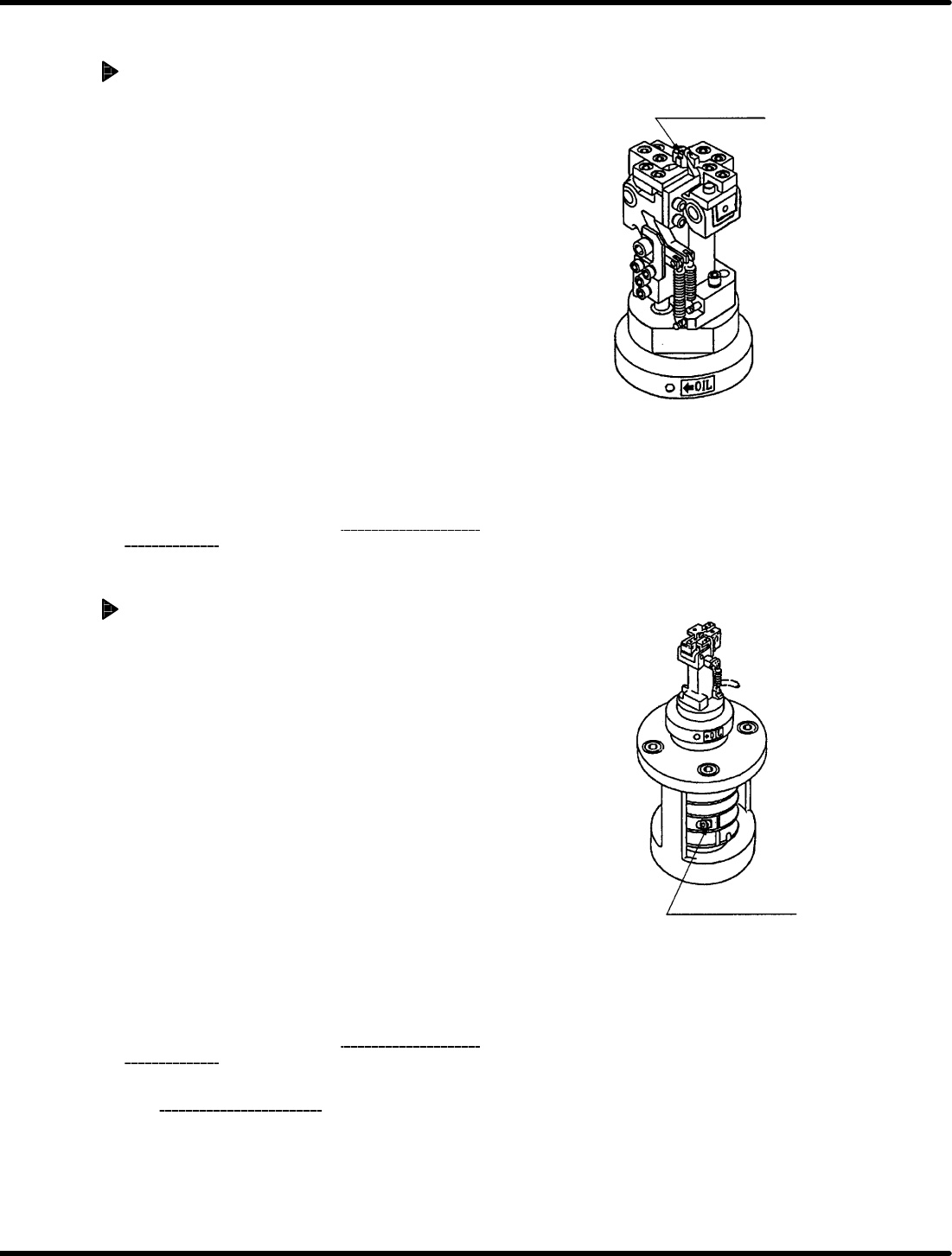
Anvil fixed blade
Anvil adjusting bolt
RH5
5.30 Anvil Height Check/Adjustment during Rising
SERVICE MANUAL
5.30−2
DA3SEC−83−9N0−A0
Anvil height adjustment during rising
When anvil too high:
1. Loosen the anvil height adjusting bolt (2−M6).
2. Set the lever−operated dial gauge to “0” at the
bottom of the guide rail in the vicinity of the
positioning lever (reference side).
3. Slide the lever−operated dial gauge parallel to
itself and fit the measuring needle of the
lever−operated dial gauge to the PCB holder of
the anvil blade.
4. Using a copper rod, tap the anvil rotating plate
from underneath and secure the anvil height
adjusting bolt (2−M6) when the height reaches r
0.05 mm.
5. Turn the hand wheel to set the digital sequence
timer to 0q .
6. Follow steps 1 through 3 in “Anvil height
check
during rising
” again.
When anvil position is low:
1. Loosen the anvil height adjusting bolt (2−M6).
2. Set the lever−operated dial gauge to “0” at the
bottom of the guide rail in the vicinity of the
positioning lever (reference side).
3. Slide the lever−operated dial gauge parallel to
itself and fit the measuring needle of the
lever−operated dial gauge to the PCB holder of
the anvil blade.
4. Using a copper rod, tap the anvil rotating plate
from above and secure the anvil height adjusting
bolt (2−M6) when the height is within r 0.05 mm.
5. Turn the hand wheel to set the digital sequence
timer to 0q .
6. Follow steps 1 through 3 in “Anvil height
check
during rising
” again.
=CHECK=
Adjusting anvil height during rising may
change the accuracy of the guide pin upper
stopper (Refer to 5.24.) and anvil parallelism
(Refer to 5.19.). So be sure to recheck
and readjust them.
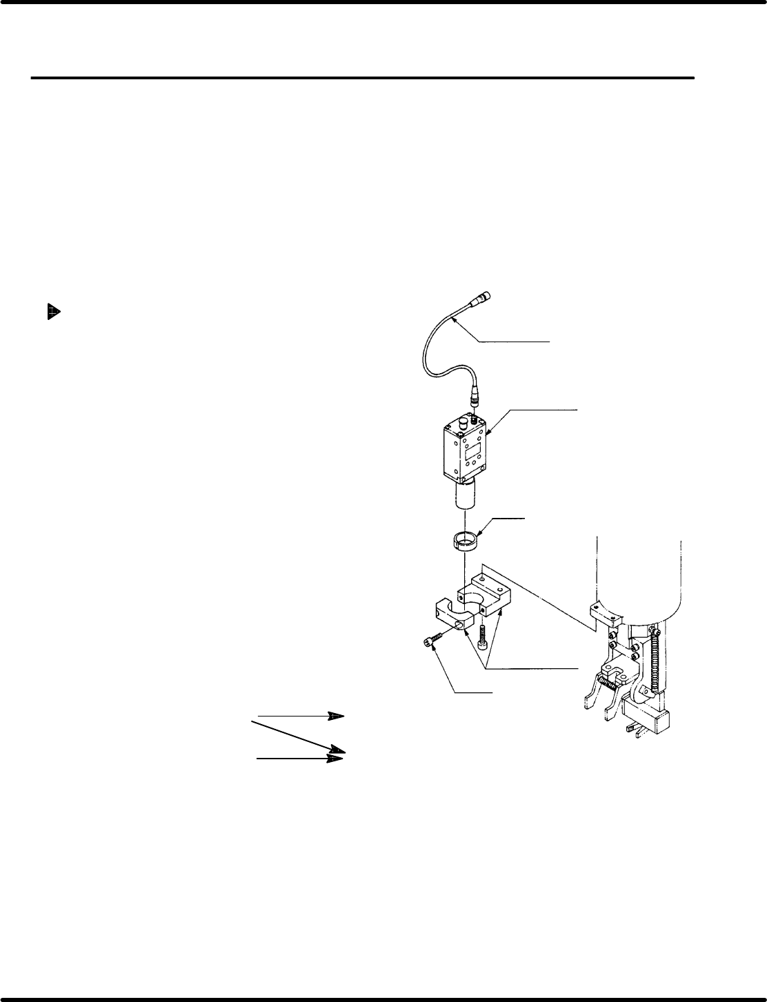
Camera cable
Camera unit
Collar
Bolt A
Camera bracket
Camera maker
Teil
(X00C86322)
NEC
(X00K84903)
Camera cable
Type L
(X00C83409)
Straight
(X00K84905)
Recognition board
Old
(X984−204)
New
(X984−211)
Compatibility: Camera cable and recognition board
5.31 Recognition Camera Lens Lamp Replacement and Adjustment
SERVICE MANUAL
RH5
5.31−1
DA3SEC−83−9P0−A0
5.31 Recognition Camera Lens Lamp Replacement and
Adjustment
DA3SEC−83−9P0−A0
Sentence No.
When to perform
x After replacing the camera lens.
x When the guide pin does not pass through
the insertion hole.
Required tools
x Allen wrench
Camera replacement
1. Disconnect the camera cable from the
camera unit.
2. Loosen bolt A (x 2) and remove camera
unit (with lens) from the camera bracket.
3. Replace camera unit.
4. Set camera unit (with lens) on the camera
bracket so that the labels facing forward.
Then, tighten bolt A (x 2).
5. Connect the camera cable to camera unit.
=CHECK=
Do not soil the camera lens or CCD
sensor.
=REFERENCE=
X984−211: If required for jumper
resetting, refer to 8.3.3.
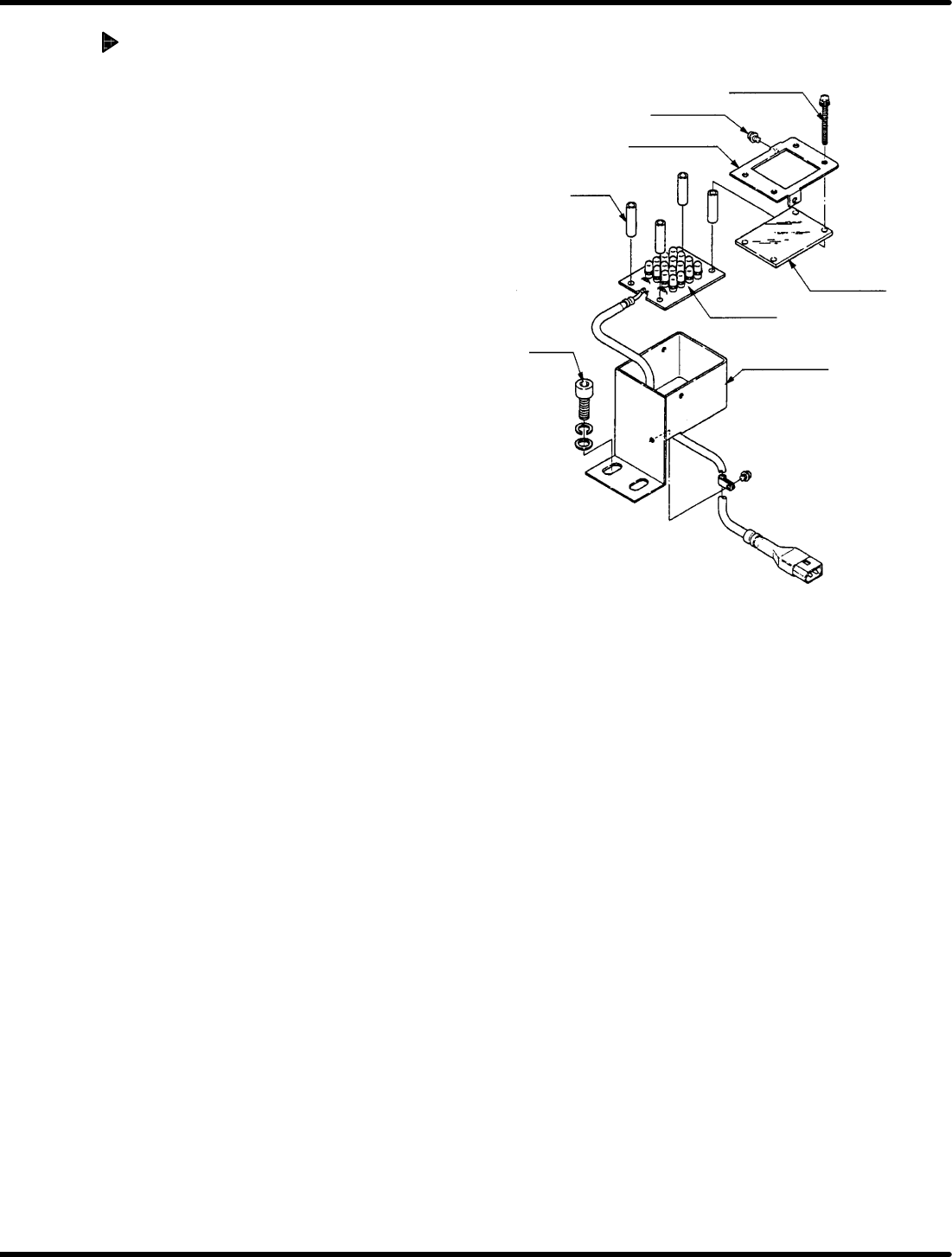
Set screw B
Set screw A
Acrylic plate
LED board
Acrylic plate
holder
Collar
Bolt
LED bracket
RH5
5.31 Recognition Camera Lens Lamp Replacement and Adjustment
SERVICE MANUAL
5.31−2
DA3SEC−83−9P0−A0
Acrylic plate replacement
1. Loosen set screw A (x 2) and B (x 4).
2. Detach plate holder to remove acrylic
plate.
3. Install a new acrylic plate and attach the
plate holder.
4. Tighten set screws A (x 2) and B (x 4).
=REFERENCE=
When changing the LED board,
replace the whole unit.