Q170226E01.pdf - 第183页
Bolt Holder Feeder carriage Pusher shaft Bolt Cylinder front/back bolt Lever B RH5 5.26 Feeder Unit Feed Pitch and Position Check and Adjustment SERVICE MANUAL 5.26−2 DA3SEC−83−9J0−A0 Feeder carriage position adjustment …
Tape waste
Cutting state
5.26 Feeder Unit Feed Pitch and Position Check and Adjustment
SERVICE MANUAL
RH5
5.26−1
DA3SEC−83−9J0−A0
5.26 Feeder Unit Feed Pitch and Position Check and
Adjustment
DA3SEC−83−9J0−A0
Sentence No.
When to perform
x When part leads do not readily fit
inside the guide chuck hole.
x When insertion errors occur frequently.
Required tools
x Allen wrench
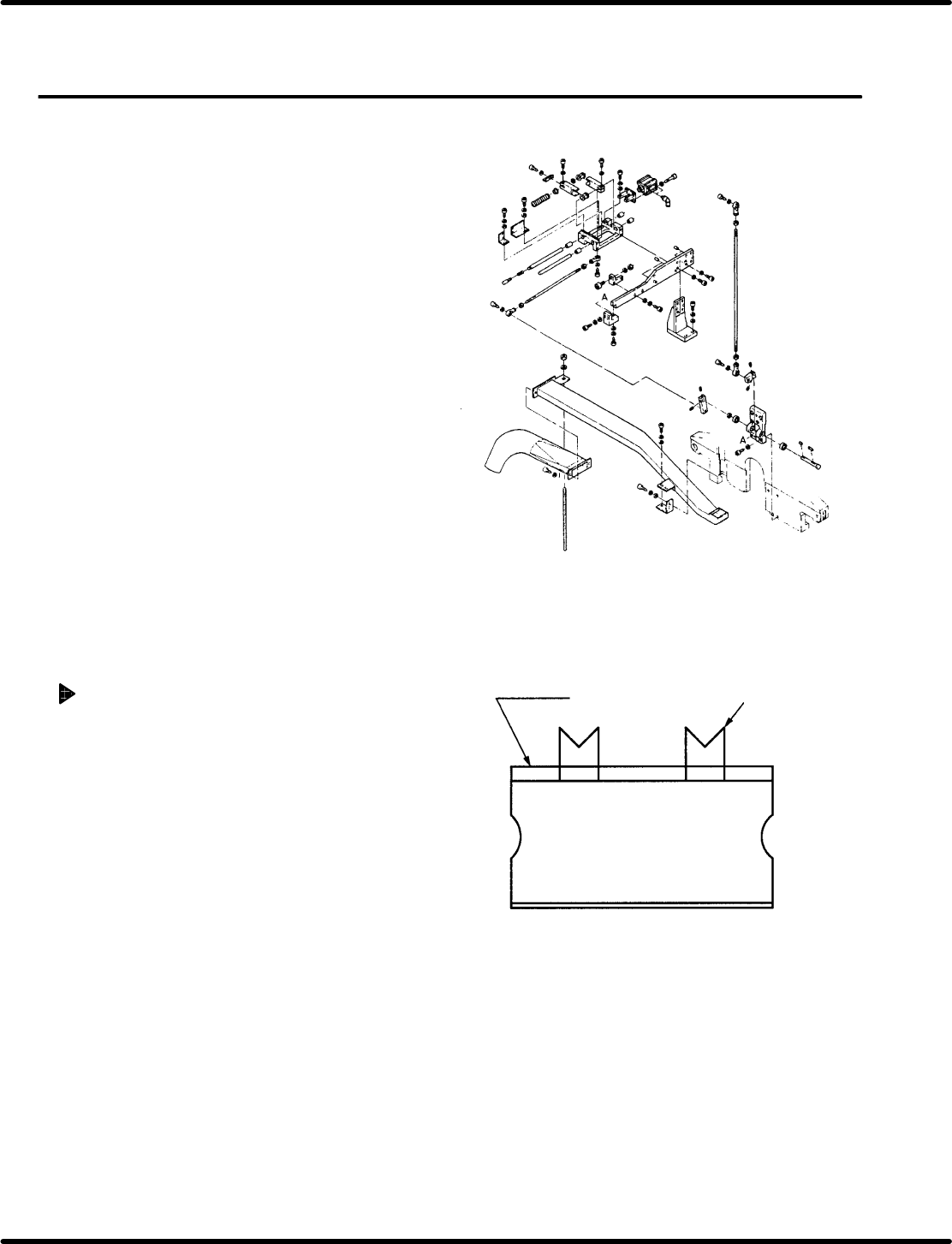
Feed pitch check
1. Set the mode to AUTO and insert
components. At this time, check that the
shape of cut lead end is as shown in the figure
(V−cut).
=CHECK=
Ensure that the components to be inserted
have been checked with a taping gauge.
=REFERENCE=
Use a 5.0 mm parts cassette when
making checks.
Bolt
Holder
Feeder
carriage
Pusher shaft
Bolt
Cylinder front/back
bolt
Lever B
RH5
5.26 Feeder Unit Feed Pitch and Position Check and Adjustment
SERVICE MANUAL
5.26−2
DA3SEC−83−9J0−A0
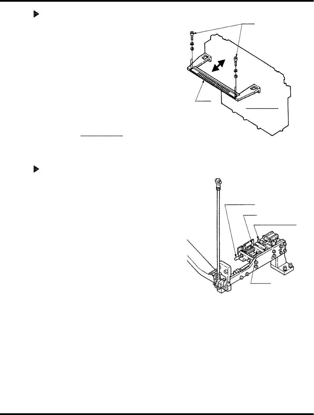
Feeder carriage position
adjustment
1. Loosen the installation bolt (x 4) fixing the
feeder carriage holder in place. Adjust the
holder to the left and right until feed position is
correct (V−cut shape).
=REFERENCE=
Adjust so that the holders at the right and
left ends are parallel to one another.
Ex. If the lead of the Z axis No. 1 has a
V−cut shape but that of No. 60 doesn’t,
loosen the installation bolt fixing the
holder on the Z60 side and adjust it
conforming to No. 1 as the reference.
2. After adjusting, adjust the feeder
to make sure
the feed pitch and the feeder carriage position.
Adjusting feed pitch (Cam feed
adjustment)
1. Set the parts cassette to the Z axis No. 1.
=REFERENCE=
Use a 5.0 mm parts cassette when
making adjustment.
2. Turn ON the FEED LOCK RELEASE on the
sub−control panel.
3. Turn the hand wheel to set the digital
sequence timer to 290q.
=REFERENCE=
Setting to 290 q enables to obtain the
correct feed pitch.
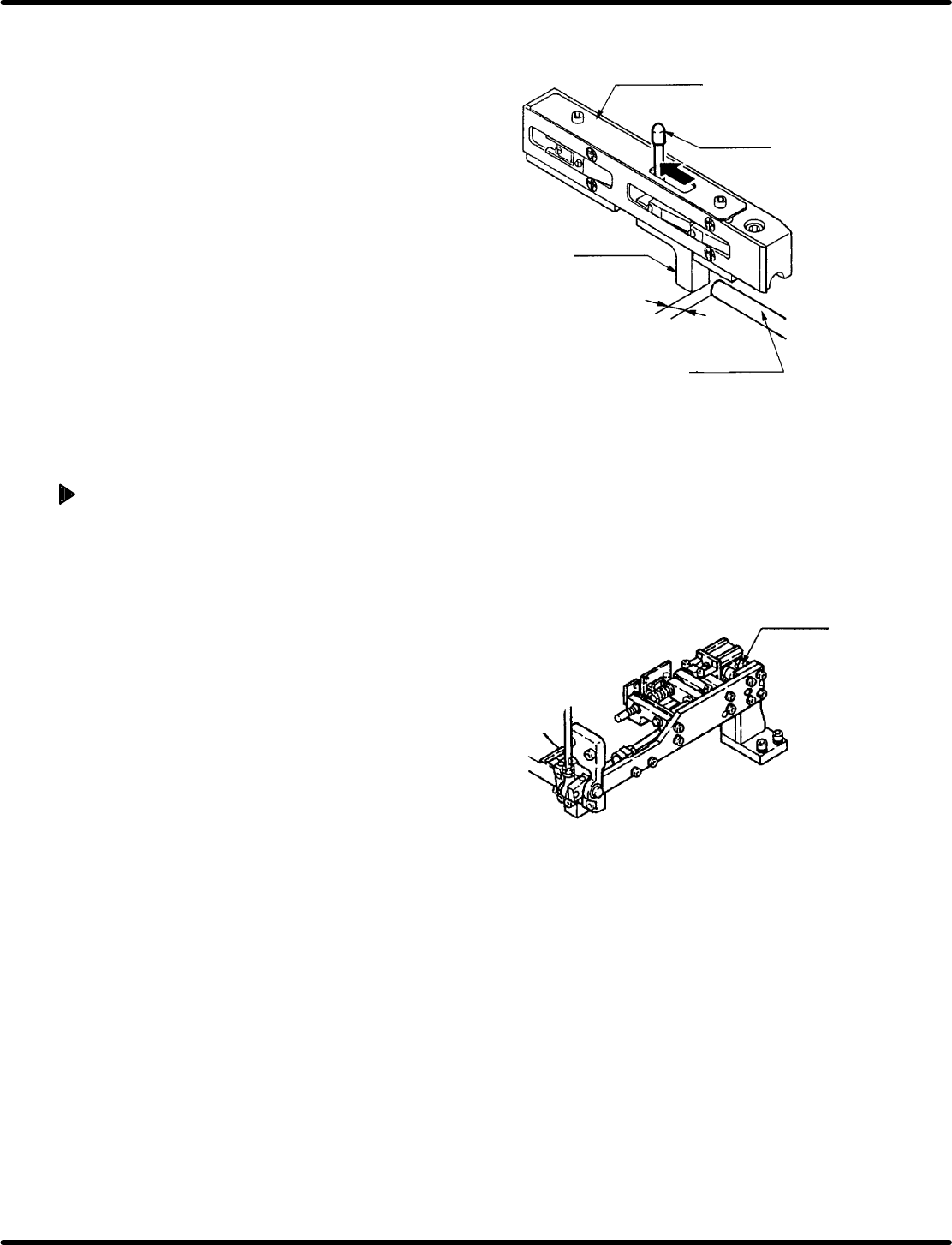
Parts casette
Spring pin
Feed slide
Pusher shaft
Clearance
1.1 mm H 0.1 mm
Cylinder
front/back bolt
5.26 Feeder Unit Feed Pitch and Position Check and Adjustment
SERVICE MANUAL
RH5
5.26−3
DA3SEC−83−9J0−A0
4. Move the spring pin completely in the direction of
arrow and check that the clearance between the
feed slide and pusher shaft is 1.1r0.1 mm using a
thickness gauge when it stops.
=REFERENCE=
The parts cassette has two types; new and old.
Factory−equipped cassettes are the new type.
Clearance of the old type cassettes shall be
0.6r0.1 mm.
5. If the correct clearance cannot be obtained, loosen
the bolts to disengage the pusher shaft.
6. Move the pusher shaft to−and−fro to adjust the
clearance.
7. After adjusting, retighten the bolts and secure the
pusher shaft.
Adjusting feed (Cylinder feed)
1. Turn the hand wheel to set the digital sequence
timer to 0q .
2. Turn OFF the FEED LOCK RELEASE on the
sub−control panel and then turn ON the PARTS
FEEDER.
3. Move the spring pin in the direction of arrow and
check that the clearance between the feed slide
and pusher shaft is 1.1r0.1 mm using a thickness
gauge when it stops.
4. If the correct clearance cannot be obtained, loosen
the front and rear bolts of the cylinder and then
move the cylinder to and fro to adjust the feed
clearance.
5. After adjusting, retighten the bolts and fix the
cylinder.