Q170226E01.pdf - 第297页
RH5 8.2 List of Software Settings SERVICE MANUAL 8.2−8 DA3SEC−85−470−B0 = MEMO =

8.2 List of Software Settings
SERVICE MANUAL
RH5
8.2−7
DA3SEC−85−470−B0
=REFERENCE=
* Machine setting can be done with the following data settings:
x Machine not having the recognition unit:
Self−correction board connection option SW: 0
Pulse motor board connection option SW: 0
Number of cameras: 0
Camera installation position: 0
x Machine having the recognition unit with fixed camera:
(1) Camera is fixed at insertion position (single board flow)
Self−correction board connection option SW: 1
Pulse motor board connection option SW: 0
Number of cameras: 1
Camera installation position: 1
(2) Camera is fixed at recognition position (double board flow)
Self−correction board connection option SW: 1
Pulse motor board connection option SW: 0
Number of cameras: 1
Camera installation position: 2

RH5
8.2 List of Software Settings
SERVICE MANUAL
8.2−8
DA3SEC−85−470−B0
= MEMO =
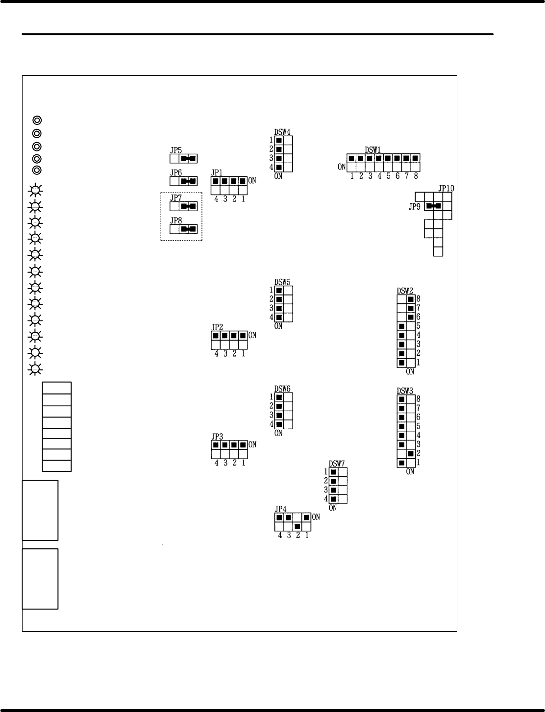
8.3 List of Jumper Switch Settings
SERVICE MANUAL
RH5
8.3−1
DA3SEC−85−540−B0
8.3 List of Jumper Switch Settings
DA3SEC−85−540−B0
Sentence No.
8.3.1 CNC−4S (I) Board Setting
CNC−4S (I)
TP4 4−axis voltage terminal
TP3 3−axis voltage terminal
TP2 2−axis voltage terminal
TP1 1−axis voltage terminal
TPG Ground terminal
LED 12 4−axis origin
LED 11 3−axis origin
LED 10 2−axis origin
LED 9 1−axis origin
LED 8 4−axis in operating
LED 7 3−axis in operating
LED 6 2−axis in operating
LED 5 1−axis in operating
LED 4 Master general purpose LED
LED 3 Master general purpose LED
LED 2 Master general purpose LED
LED 1 Master general purpose LED
VRB4
VRB3
VRB2
VRA1
VRA2
VRA3
VRA4
VRB1
4−axis offset
3−axis offset
2−axis offset
1−axis offset
4−axis gain
3−axis gain
2−axis gain
1−axis gain
CN2
CN1