Q170226E01.pdf - 第181页
RH5 5.25 Feeder Carriage Origin Position Check and Adjustment SERVICE MANUAL 5.25−2 DA3SEC−83−9H0−A0 Origin position adjustment (When deviation is 1.0 mm or more.) 1. Input “0” to “Z axis origin offset”. 2. Change the mo…
No.2 parts
cassette
Transfer chuck
No.1 parts
cassette
Cover
Bolt B
Timing pulley
(motor side)
Timing pulley
(ball screw side)
timing belt
5.25 Feeder Carriage Origin Position Check and Adjustment
SERVICE MANUAL
RH5
5.25−1
DA3SEC−83−9H0−A0
5.25 Feeder Carriage Origin Position Check and
Adjustment
DA3SEC−83−9H0−A0
Sentence No.
When to perform
x When leads of cut parts are bent.
x When insertion errors occur frequently.
Required tools
x Allen wrench
x Screwdriver
Origin position check
1. Turn the hand wheel until the cam shaft
is at approximately the 0q position on the
digital sequence timer.
2. Return the parts feeder to its origin in
manual mode.
3. From the rear of the machine, check the
midpoint between to the No. 1 and No. 2
parts cassettes (parts feeding side) is at
the center of the transfer chuck.
Origin position adjustment
(When deviation is 1.0 mm or
less.)
1. Set the mode to “SEMI” o “1BLOCK” o
“MANUAL” o “1BLOCK”. Then press
“REQ” o “F6” o “F1” o “F2” in order.
2. Input the amount of deviation to “Z axis
origin offset”.
3. Check the origin position again.

RH5
5.25 Feeder Carriage Origin Position Check and Adjustment
SERVICE MANUAL
5.25−2
DA3SEC−83−9H0−A0
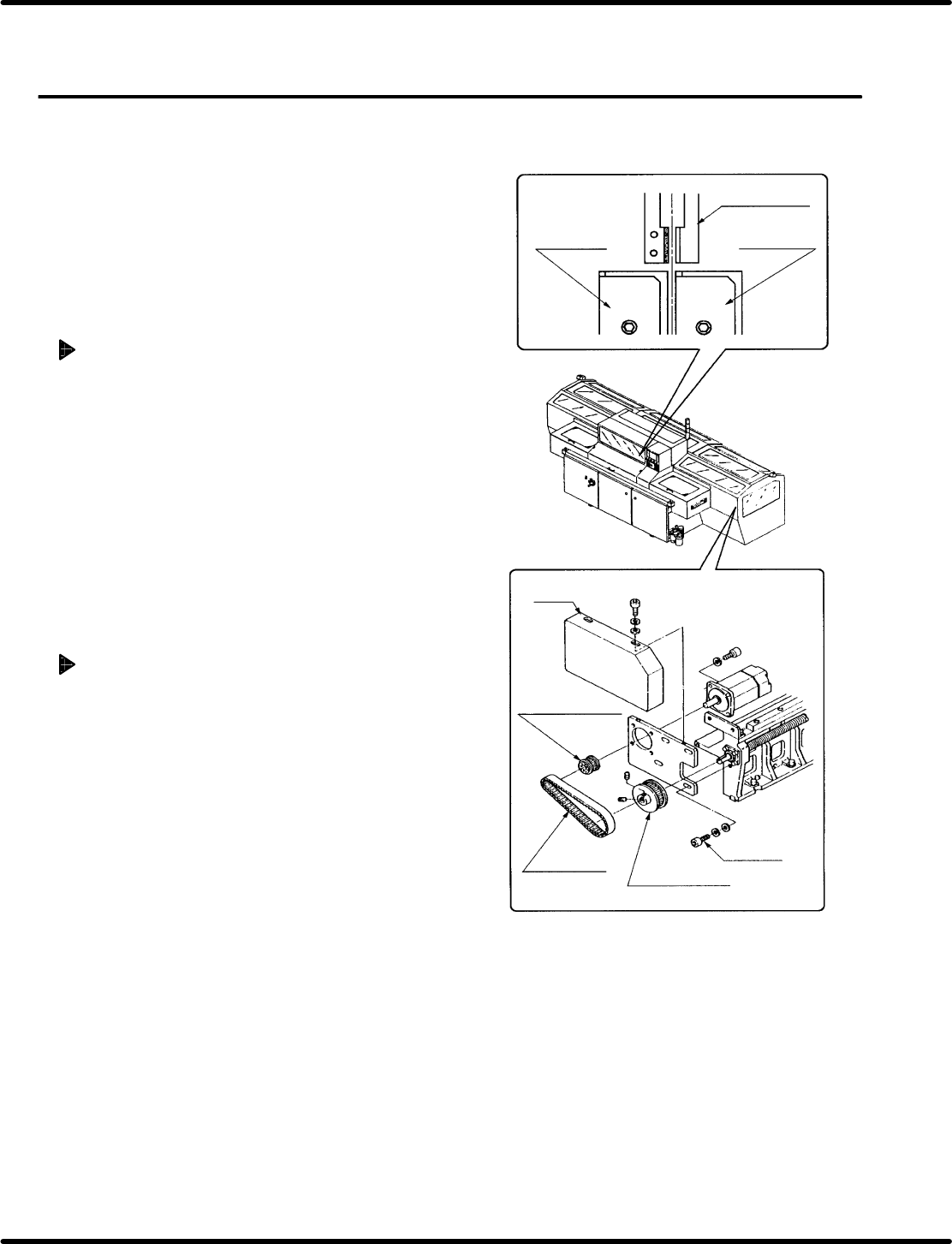
Origin position adjustment (When
deviation is 1.0 mm or more.)
1. Input “0” to “Z axis origin offset”.
2. Change the mode from “MANUAL” to “1BLOCK”
and return the feeder to the origin.
3. Disengage the bolt B (4−M10) and detach the
timing belt.
4. Turn timing pulleys until the origin position is
placed at the center to place the timing belt on
the pulleys. Then retighten the bolt B (4−M10).
5. Perform origin return again to check for
the
origin
position.
=REFERENCE=
Inputting 1.0 mm or more to the “Z axis origin
offset” may cause the Z axis to reach
upper/lower quickly.
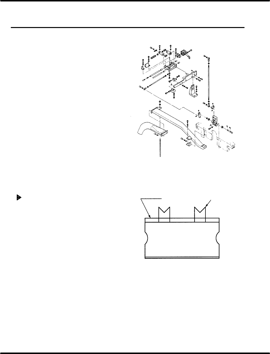
Tape waste
Cutting state
5.26 Feeder Unit Feed Pitch and Position Check and Adjustment
SERVICE MANUAL
RH5
5.26−1
DA3SEC−83−9J0−A0
5.26 Feeder Unit Feed Pitch and Position Check and
Adjustment
DA3SEC−83−9J0−A0
Sentence No.
When to perform
x When part leads do not readily fit
inside the guide chuck hole.
x When insertion errors occur frequently.
Required tools
x Allen wrench
Feed pitch check
1. Set the mode to AUTO and insert
components. At this time, check that the
shape of cut lead end is as shown in the figure
(V−cut).
=CHECK=
Ensure that the components to be inserted
have been checked with a taping gauge.
=REFERENCE=
Use a 5.0 mm parts cassette when
making checks.