Q170226E01.pdf - 第293页
RH5 8.2 List of Software Settings SERVICE MANUAL 8.2−4 DA3SEC−85−470−B0 Real ROM address Description Default 0FFFD4 (068054) 7FFD4 Bad mark recognition option SW (When this SW is OFF , finding bad mark recognition comman…
8.2 List of Software Settings
SERVICE MANUAL
RH5
8.2−3
DA3SEC−85−470−B0
Real
ROM
address
Description Default
0FFFBA
(06803A)
7FFBA Width adjusting axis motor connection SW (Also indicates the presence
of semiauto/auto width adjusting motor.)
Bit 0: Width adjust loader axis
Bit 1: Width adjust X−Y table axis
Bit 2: Width adjust unloader axis
Bit 3: Width adjust reference pin axis
Bit value = 1: Axis exists
0: no axis
(Ex.) Loader and unloader axes only = 05
All axes except reference pin axis = 07
4 axes (all axes) = 0F
0
0FFFBC
(06803C)
7FFBC Component invert unit type SW (Available only when the machine is
RHXP and the invert unit is connected.)
0: 5.0/7.5 mm
1: 7.5/10 mm
0
0FFFBE
(06803E)
7FFBE M1000 l M10 data convert command SW
(When converting P770 NC data into P791, if this SW is 1, M100 data
will be converted to M10 and vice versa for RHP model.)
0: M10 l M100 without conversion
1: M10 l M100 convert available
0
0FFFC0
(068040)
7FFC0 Applicable SW for special 2.5/3.5 mm pitch
(Enables component insertion on 2.5/3.5 mm pitch exclusive model
using M1 command.)
0
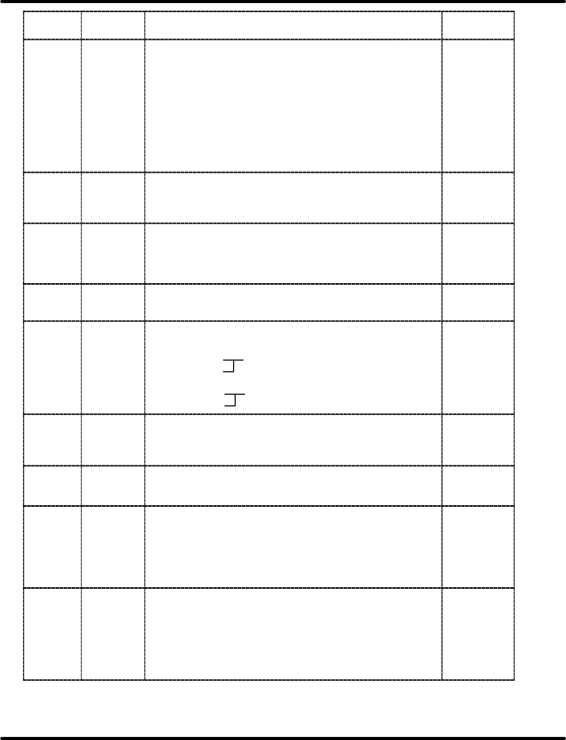
0FFFC2
(068042)
0FFFC3
(068042)
7FFC2
7FFC3
Special 2.5/3.5 mm pitch data
(Available only when the above special switch is ON.)
2.5 mm pitch data
7FFC2: C4 9C4 (2500)
7FFC3: 09
3.5 mm pitch data
7FFC2: AC DAC (3500)
7FFC3: 0D
AC
0D
0FFFC4
(068044)
7FFC4 Reverse board flow (L o R) machine SW
0: Flow direction L m R (standard type)
1: Flow direction L o R (standard type)
2: Flow direction L o R (special version)
0
0FFFC8
(068048)
7FFC8 Graphic (GRA) board connection option SW
0: Not connected
1: Connected
0
0FFFCA
(06804A)
7FFCA NG board punching unit connection option SW
(Indicates whether or not the board punching unit is connected to RH5.
When skip recovery mode is selected, the punching unit is used at the
unloader exit to punch (or mark) the boards out which have been
skipped due to insertion error.)
0: Not connected
1: Connected
0
0FFFCC
(06804C)
7FFCC PH error detection option SW
(This switch may bring the machine to a 1 block stop when the
component sensor detects a component by mistake when the CS5
sensor is ON. It sets a flag on SEQ link table. This flag can be
overwritten on the monitoring screen, just the same as ignoring
insertion detection.)
0: PH error invalid
1: PH error valid
1

RH5
8.2 List of Software Settings
SERVICE MANUAL
8.2−4
DA3SEC−85−470−B0
Real
ROM
address
Description Default
0FFFD4
(068054)
7FFD4 Bad mark recognition option SW
(When this SW is OFF, finding bad mark recognition commands (V10)
in NC data may cause a syntax error.)
0: V10 command invalid
1: V10 command valid
0
0FFFD6
(068056)
7FFD6 Pattern command option SW
(When this SW is OFF, finding pattern commands (S&R, P&R) in NC
data may cause a syntax error.)
00H: Pattern command (M901, 902) invalid
01H: Pattern command (M901, 902) valid
(Polar coordinate not allowed)
81H: Pattern command (M901, 902) valid
(Polar coordinate permissible)
01
0FFFD8
(068058)
7FFD8 1st insertion hole recognition command combination option SW
(When this SW is OFF, combination of all holes (optional hole) and 1st
insertion hole recognition in NC data will cause a syntax error if PC
board flow type is double.)
0: Invalid
1: Valid
1
0FFFDA
(06805A)
7EEDA Reference hole recognition combination option SW
0: Not available
1: Available
1
0FFFDE
(06805E)
7FFDE Insertion error position display function option SW
0: Not available
1: Available
0
0FFFDF
(06805F)
7EEDF Walking beam unit connection option SW
0: Not connected
1: Connected
0
0FFFE0
(068060)
7FFE0 XY table quadruple option SW
(Enables 1 pulse resolution of XY table to be changed from 1/100 to
2.5/1000 only in case of CNC−4S board.)
0: XY table 1 multiplication
1: XY table 4 multiplication
0
0FFFE2
(068062)
7FFE2 Block alternate option SW
0: Block alternate disabled
1: block alternate available
0
0FFFE4
(068064)
7FFE4 Insertion rate
0: Includes insertion error counts during auto recovery.
1: Excludes insertion error counts during auto recovery.
2: Supports total insertion rate
2
0FFFEA
(06806A)
7FFEA Board flow dedicated model option SW
0: Single/double board flow common use
1: Single board flow only
2: Double board flow only
1
8.2 List of Software Settings
SERVICE MANUAL
RH5
8.2−5
DA3SEC−85−470−B0
Real
ROM
address
Description Default
0FFFEC
(06806C)
7FFEC Transfer complete (R1RD) command output to host SW
0: Does not output R1LD
1: Outputs R1LD
1
0FAD14
(003B44)
0FAD15
(003B45)
7AD14
7AD15
Camera axis maximum speed (PTP) Low
Camera axis maximum speed (PTP) High
40
01
0FAD16
(003B46)
0FAD17
(003B47)
7AD16
7AD17
Camera axis maximum speed (JOG) Low
Camera axis maximum speed (JOG) High
16
00
0FAD18
(003B48)
0FAD19
(003B49)
7AD18
7AD19
Camera axis acceleration (ORG) Low
Camera axis acceleration (ORG) High
0A
00
0FAD1A
(003B4A)
7AD1A Camera axis acceleration (PTP) 40
0FAD1B
(003B4B)
7AD1B Camera axis maximum speed (ORG) 20
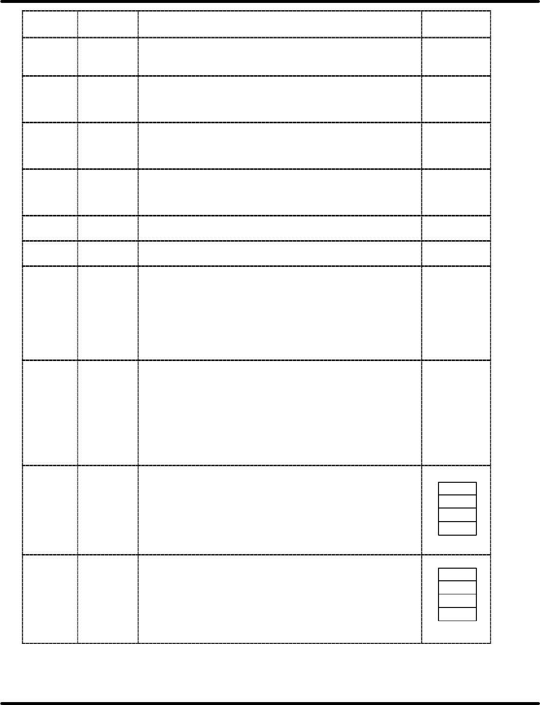
0FAD22
(003B52)
0FAD23
(003B53)
0FAD24
(003B54)
0FAD25
(003B55)
7AD22
7AD23
7AD24
7AD25
ZL axis standby coordinate position
30−feeder *
2
= 1637.000 mm (88H, FAH, 18H, 00H)
40−feeder *
2
= 2685.000 mm (48H, F8H, 28H, 00H)
RHII = 2689.000 mm (E8H, 07H, 29H, 00H)
E8
07
29
00
0FAD26
(003B56)
0FAD27
(003B57)
0FAD28
(003B57)
0FAD29
(003B59)
7AD26
7AD27
7AD28
7AD29
ZR axis standby coordinate position
30−feeder *
2
= 0.000 mm (00H, 00H, 00H, 00H)
40−feeder *
2
= 0.000 mm (00H, 00H, 00H, 00H)
00
00
00
00
0FAD2E
(003B5E)
0FAD2F
(003B5F)
0FAD30
(003B60)
0FAD31
(003B61)
7AD2E
7AD2F
7AD30
7AD31
Distance from head to camera origin (X direction)
Current model: 380.000 mm (60H, CCH, 05H, 00H)
Standard model: 380.000 mm (60H, CCH, 05H, 00H)
Large model: 558.000 mm (B0H, 83H, 08H, 00H)
60
CC
05
00
0FAD32
(003B62)
0FAD33
(002B63)
0FAD34
(003B64)
0FAD35
(003B65)
7AD32
7AD33
7AD34
7AD35
Distance from head to light source (2) (X direction)
Current model: 086.000 mm (F0H, 4FH, 01H, 00H)
Standard model: 086.000 mm (F0H, 4FH, 01H, 00H)
Large model: 086.000 mm (F0H, 4FH, 01H, 00H)
RHII: −90.000 mm (70H, A0H, FEH, FFH)
70
A0
FE
FF