Cadence_16.6高速电路板设计与仿真.pdf - 第377页
1 ) S t a r t i n g C a d e n c e L o g i c I m p o r t 。 2 ) n e t r e v c o m p l e t e d s u c c e s s f u l l y , u s e V i e w l o g t o r e v i e wt h e l o g f i l e 。 3 ) O p e n i n g e x i s t i n g d e s i g n…
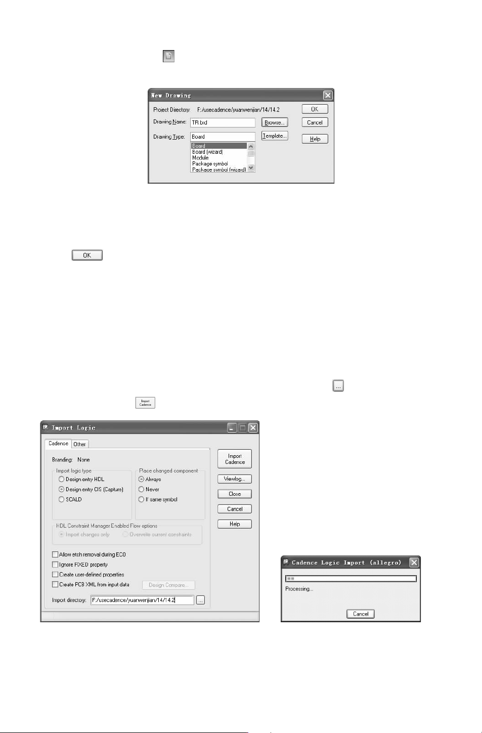
栏中的 “New (新建)” 按钮 ,弹出如图 12-102所示的 “NewDrawing(新建图样)” 对
话框。
图 12-102 “NewDrawing(新建图样)”对话框
在 “DrawingName(图样名 称)” 文 本 框 中 输 入 图 样 名 称 “TR”;在 “DrawingType
(图样类型)” 下拉列表中选择图样类型 “Board”。
单击 按钮,结束对话框,进入设置电路板的工作环境。
2.导入原理图网络表信息
选择菜单栏中的 “File(文件)”
→
“Import(导入)”
→
“Logic(原理图)” 命令,弹
出如图 12-103所示的 “ImportLogic(导入原理图)”对话框。打开 “Cadence” 选项卡,导
入在 Capture里的输出网络表。
在 “Importlogictype(导入的原理图类型)” 选项组下勾选 “DesignentryCIS(Cap-
ture)” 选项;在 “Placechangedcomponent(放置修改的元件)” 选项组下默认选择 “Al-
ways
(总是)”。
在 “Importdirectory(导入路径)” 文本框中,单击右侧按钮 ,在弹出的对话框中选
择网表路径目录,单击 按钮,导入网络表,出现进度对话框,如图 12-104所示。
图 12-103 “ImportLogic(导入原理图)” 对话框 图 12-104 导入网络表的进度对话框
当执行完毕后,若没有错误,在命令窗口中显示完成信息:
563
1)StartingCadenceLogicImport。
2)netrevcompletedsuccessfully,useViewlogtoreviewthelogfile。
3)Openingexistingdesign。
4)netrevcompletedsuccessfully,useViewlogtoreviewthelogfile。
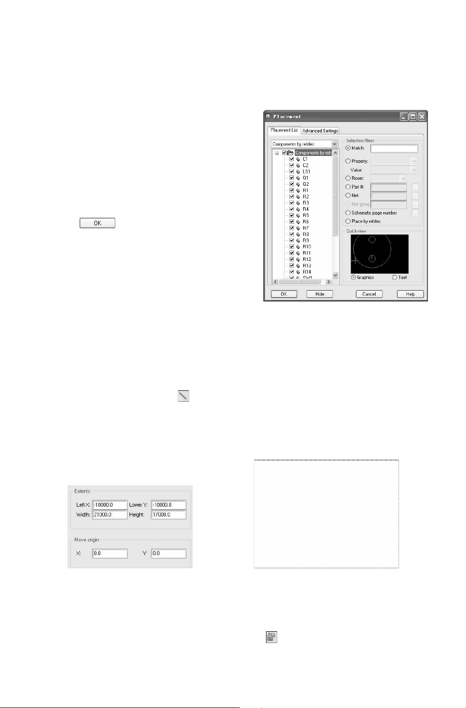
图 12-105 PlacementList选项卡
选择菜单栏中的 “Place(放置)”
→
“Manu-
ally(手 动 放 置 )” 命 令, 弹 出 “Placement(放
置)” 对 话 框,在 “
PlacementList(放置列表)”
选项卡的下拉列表 中选择 “Componentsbyrefdes
(按照元件序号)” 选项,按照序号显示元件,如
图 12-105所示。
在列表下显示所有元件,表示元件封装导入
成功,单击 按钮,关闭对话框。
3.图样参数设置
在绘制边框前,先要根据板的外形尺寸确定
PCB工作区域的大小。
选择菜单栏中的 “Setup(设置)”
→
“Design
ParameterEditor
(设计参数编辑)” 命令,弹出如
图 12-106所示的 “DesignParameterEditor(设计
参数编辑)”对话框,打开 “Design(设计)” 选项卡,在 “Extents(图样范围)” 选项中设
置 “
LeftX”、“LowerY”、“Width”、“Height”相应的值。确定图样边框大小。
4.电路板的物理边界
选择菜单栏中的 “Add(添加)”
→
“Line(线)” 命令或单击 “Add(添加)”工具栏
中的 “AddLine(添加线)”按钮 ,依次在输入窗口输入字符: “x00”、 “ix4000”、 “iy
3000”、“ix-4000”、“iy-3000”。
绘制一个封闭的边框,完成边框闭合后,单击右键,选择快捷命令 “Done(完成)” 结
束命令。绘制完成的边框如图 12-107所示。
图 12-106 “Extents(图样范围)”选项 图 12-107 绘制边框
5.放置定位孔
选择菜单栏中的 “Place(放置)”
→
“Manually(手工放置)” 命令或单击 “Place(放
置)”工具栏中的 “PlaceManual(手工放置)” 按钮 ,弹出如图 12-108所示的 “Place-
663
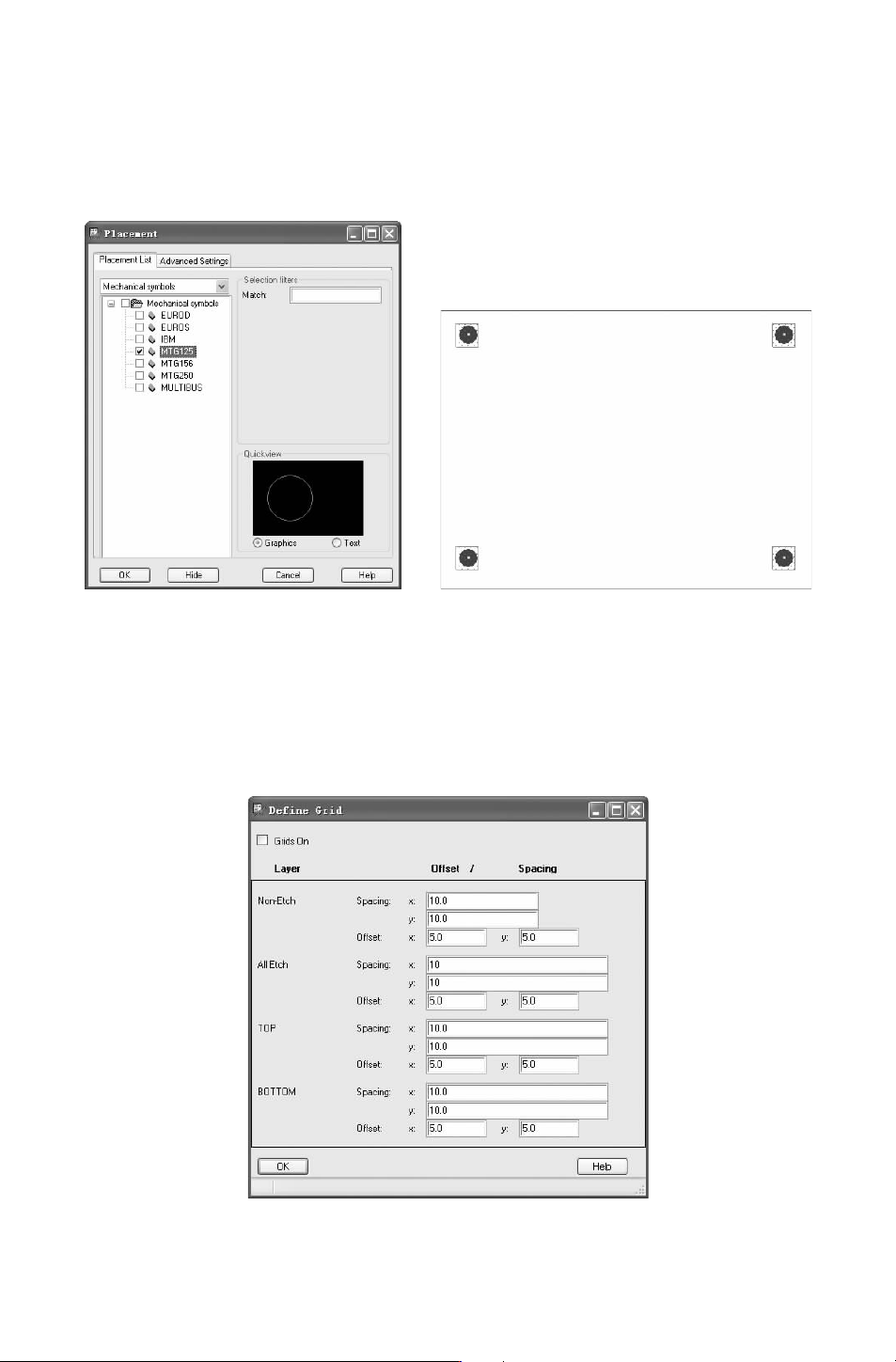
ment(放置)” 对话框,如图 12-108所示。打开 “PlacementList(放置列表)”选项卡,在
下拉列表中选择 “
Mechanicalsymbols(机械符号)” 选项,显示加载的库中的元件,勾选
“MTG125”,在信息窗口中一次输入定位孔坐标值,放 置四 个定 位孔,结果 如图 12-109
所示。
图 12-108 选择符号 图 12-109 放置定位孔
6.放置工作格点
选择菜单栏中的 “Setup(设置)”
→
“Grid(网格)” 命令,弹出如图 12-110所示
的 “DefineGrid(定义网格)” 对话框,在该对话框中主要设置显示层的偏移量和间距。
将 “Non-Etch(非布线层)”、“AllEtch(布线层)” 栅格设为 10mil,偏移量设为 5mil,
如图 12-110所示。
图 12-110 “DefineGrid(定义网格)”对话框
763