XP-142E System Reference-SYS-XP142-2.0E.pdf.pdf - 第157页
Operation Button Explanations Press this button to perform sequence data editing using the teaching function with actual machine operation. Searches the sequence data for a specified character string. Edits (at feeder se…
3. Editor
Note: The value entry fields where settings can be changed are enclosed in brackets here. However, the
settings shown in this manual are not necessarily the same as your machine specifications, so confirm the
value before making any setting changes.
3.1 Editor Screen
(ESR0703a)
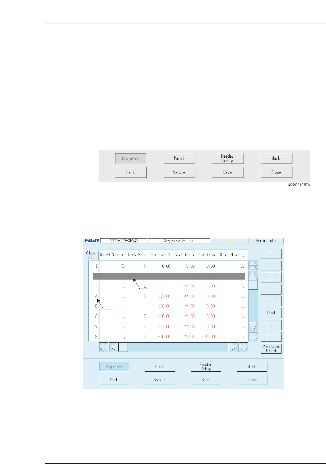
This screen is used to edit sequence, panel, feeder setup, mark, part, and nozzle data.
Procedure
1. At the [Main] screen, press [Program], [Select Program], then select the program
where editing is to occur.
2. Press [Editor] to display the following buttons at the bottom of the touch screen.
3.2 Sequence Data
(ESR0704f)
Press [Sequence] to display the following screen.
Note: When a setting is made to skip a sequence, the letters in that row appear in red.
2 0, F, -99.59, 82.96, 0.00, 0,
Data input line
Selecting area
XP2S2157Eb
Part 3 Chapter 3 Editor
Edition 2.0 3-3-1 XP-142E System Reference
Operation Button Explanations
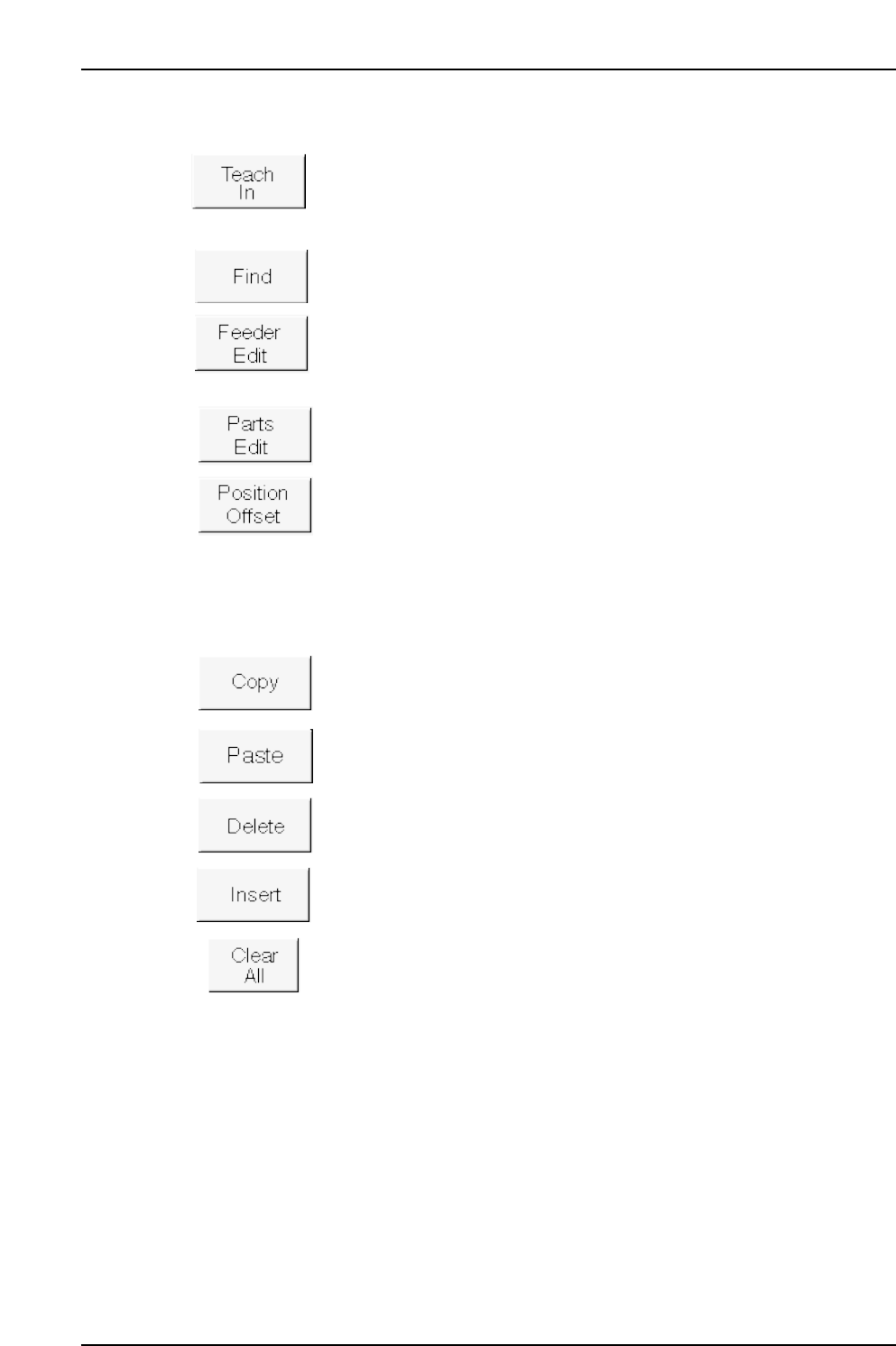
Press this button to perform sequence data editing using the teaching
function with actual machine operation.
Searches the sequence data for a specified character string.
Edits (at feeder setup screen) the feeder used at the selected line.
Edits (at part editor screen) the part to be placed at the selected line.
Offset coordinates for single boards.
The following buttons apply to the line which has been selected in the selection area at
the left side of the screen.
Copies the selected line to the clipboard.
Pastes the clipboard data above the selected line.
Deletes the selected line, and moves the subsequent lines up to fill the
vacated space.
Inserts a new (blank) line above the selected line.
Cancels all selections.
Part 3 Chapter 3 Editor
Edition 2.0 3-3-2 XP-142E System Reference

Setting Item Explanations
Selection area (sequence No.)
Display the sequence number.
Board No. (0 ~ 255)
This is the ID number of each board in cases where a single panel (PCB) contains a
number of same-pattern boards. This item should be set to “0” when producing panels
which do not contain multiple boards. When producing a multi-board panel, the
necessary sequence data is created in one of the following ways:
• A board No. of “1” is specified for a given board, and the sequence data is entered
manually for that board only. The machine then subjects this data to expander
processing to automatically generate the sequence data for the number of boards
being produced.
• The board Nos. and sequence data for all the boards are entered manually.
Sequence Type
Select the sequence type from the following.
B: Board skip mark reading sequence
D: Placement sequence
F: Fiducial mark reading sequence
X-coordinate
Enter the panel’s X-direction coordinate.
If a coordinate is entered relative to a reference point other than the Fuji program’s origin
point (-5 mm in X-direction, or 5 mm in Y-direction, measured from panel’s bottom right
corner), an X-offset value must be entered in the panel data as an “origin offset X”
setting. (-650.00 mm ~ 650.00 mm)
Y-coordinate
Enter the panel’s Y-direction coordinate.
If a coordinate is entered relative to a reference point other than the Fuji program’s origin
point (-5 mm in X-direction, or 5 mm in Y-direction, measured from panel’s bottom right
corner), an Y-offset value must be entered in the panel data as an “origin offset Y”
setting. (-650.00 mm ~ 650.00 mm)
Angle
Enter the angle of the part to be placed. Use the part angle viewed when editing the part,
as a reference.
Stage No.
Each of the machine sides where MFU part supply units are set is referred to as a
“stage”. On XP series machines, the front side is “stage 1”, and the rear side is “stage 2”.
Enter stage numbers which correspond to the sides where parts are being supplied.
(1, 2)
Slot No.
Slots are defined as the location of tape feeders loaded on the part supply units.
Enter a slot no. in which a part can be loaded. (1 ~ 50)
Mark No.
Specifies the mark number. Any number may be entered, provided that it does not
duplicate an existing number. Mark numbers can only be specified at the mark reading
sequence. (1 ~ 255)
Part 3 Chapter 3 Editor
Edition 2.0 3-3-3 XP-142E System Reference