XP-142E System Reference-SYS-XP142-2.0E.pdf.pdf - 第182页
Setting Item Explanations Part Type Name Specifies the part type name. No more than 30 characters may be used in this name. Note: The following characters may not be used in file names: ( : \ / ; * ? “ < > | ) Also…
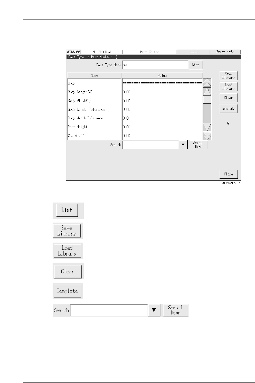
3.6.1 Part Type Editing
The part type editor is used to set part information.
Operation Button Explanations
Displays a list of part types used by the production program which is
currently opened in the editor.
Saves edited part type data to the library.
Loads a part type which is saved in the library.
Clears the setting data.
Press to perform template editing using the template editor.
Item searches display the specified data name. Press the black arrow-mark key to
display a classification list. A search can also be performed by entering the part number
name directly from the keyboard. Press the [Scroll Down] key to execute a search in the
“top to bottom” direction.
Part 3 Chapter 3 Editor
Edition 2.0 3-3-26 XP-142E System Reference

Setting Item Explanations
Part Type Name
Specifies the part type name. No more than 30 characters may be used in this name.
Note: The following characters may not be used in file names: ( : \ / ; * ? “ < > | ) Also, characters
(˜ .) may not be used at the beginning of the file names.
Part type data consists of the following five categories.
• Body
• Lead
• Element
• Process
• Vision
Body
Body Length (X)
Specifies the X-direction length of the part’s basic shape. (0.01 mm ~ 20.00 mm)
Body Width (Y)
Specifies the Y-direction length of the part’s basic shape. (0.01 mm ~ 20.00 mm)
Body Length Tolerance
Specifies the body’s Y-direction size tolerance. Specify this setting only for parts
(without leads as 2125, 3216, etc.) inspected using vision type 10 (Rect). It is not required
for parts (with leads SOP, QFP, etc.) inspected using vision type other than 10. A
tolerance error occurs when the detected part size exceeds this tolerance value. This
tolerance value should generally be about 10% of the body size. (0.00 mm ~ 9.99 mm)
The Body Length Tolerance check is not completed if the value is set to 0.0.
Body Width Tolerance
Specifies the body’s Y-direction size tolerance. Specify this setting only for parts
(without leads as 2125, 3216, etc.) inspected using vision type 10 (Rect). It is not required
for parts (with leads SOP, QFP, etc.) inspected using vision type other than 10. A
tolerance error occurs when the detected part size exceeds this tolerance value. This
tolerance value should generally be about 10% of the body size. (0.00 mm ~ 9.99 mm)
The Body Width Tolerance check is not completed if the value is set to 0.0.
Part 3 Chapter 3 Editor
Edition 2.0 3-3-27 XP-142E System Reference
Part 3 Chapter 3 Editor
Edition 2.0 3-3-28 XP-142E System Reference
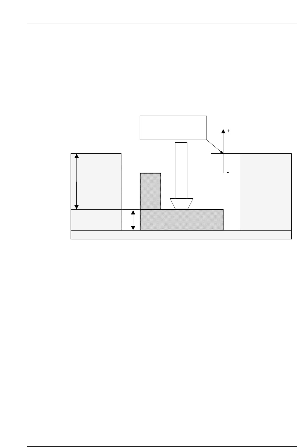
Part Height
Specifies the part height (thickness from nozzle pick-up face to part’s bottom face). The
height includes the lead length. (0.01 mm ~ 6.0 mm)
(Refer to the illustration below. The “Pickup Point Offset Z” and “Placing Offset Z”
items are explained later in this manual.)
* The top face of the tape and tray is the pickup reference position.
* Z-axis height at pickups:
(For tape) Pickup position reference + Pickup Point Offset Z
(For tray) Pickup position reference + Tray Pick Offset Z
Lead
Pitch Tolerance
Specifies the lead pitch tolerance range. (0% to 100%)
Vision Type 100 is supported. A setting of “0%” is processed as “30%”.
Measure Point of Lead
Specifies the position where vision processing is to occur as a percentage of the total lead
length, measured from the lead tip. If “0” is entered, then vision processing occurs at the
position on the lead 20% of the total lead length from the lead tip. This setting is only
used with vision types 20 and 100. (0 – 100%)
Pickup position reference
Pickup Point Offset Z origin
Tray Pick Offset Z origin
Pickup Point
Offset Z
(for feeder)
Tray Pick
Offset Z
(for tray)
Part Height
MCSX330Ea