XP-142E System Reference-SYS-XP142-2.0E.pdf.pdf - 第52页
2.1.12 Other Operation Settings The procedure for setting other operation settings is given below. Procedure 1. At the [Main] screen, select [Maintenance A] - [Operation Settings] to display the [Operation Conditions Set…
2.1.11 Local Verify (Optional)
This is a part set position check function (optional) which prevents the wrong parts from
being set in the machine slots. The setting procedure for this function is given below. (A
setup procedure is required in order to use this local verify function.)
Procedure
1. At the [Main] screen, select [Maintenance A] - [Operation Settings] to display the
[Operation Settings] screen.
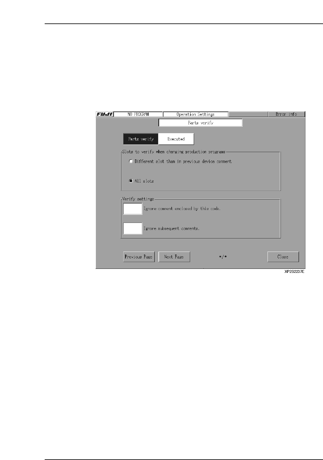
2. Press the [Next Page] button to display the [Parts Verify] screen.
3. In the textbox next to the “Parts Verify” item, specify whether or not the verify
function is to be used. If “Executed” is selected, continue with the settings
described below.
4. Select whether or not a slot verify operation is to occur under one of the displayed
conditions.
Different slot than in previous device comment: Only slots which are different
from those used by the previous
production program are checked.
All slots: All slots are checked.
5. When a portion of a barcode reading is to be ignored, that portion can be skipped
by using a 1-digit ASCII Code.
Ignore comment enclosed by this code:
The portion surrounded between this ASCII code is ignored.
Ex. If a slash “/” is specified in the field for “Ignore comment enclosed by this
code,” then “12345/6789/0123” will be read as “0123450123”. However, if
only one symbol is used (not a pair), then the numbers after the symbol will
be ignored. Thus, “12345/6789/0123/456” will be read as “123450123”.
Ignore subsequent comments:
All comment which follow the ASCII code are ignored.
[Ex] if a “/” is used as the ASCII code, a “12345/6789/0123” comment will be
interpreted as “12345”.
Part 2 Chapter 2 Settings Prior to Start Production
Edition 2.0 2-2-9 XP-142E System Reference
2.1.12 Other Operation Settings
The procedure for setting other operation settings is given below.
Procedure
1. At the [Main] screen, select [Maintenance A] - [Operation Settings] to display the
[Operation Conditions Settings] screen.
2. If the local verify function is not being used, press the [Next Page] button 3 times
to display the [Other] screen. If the verify function is being used, press the [Next
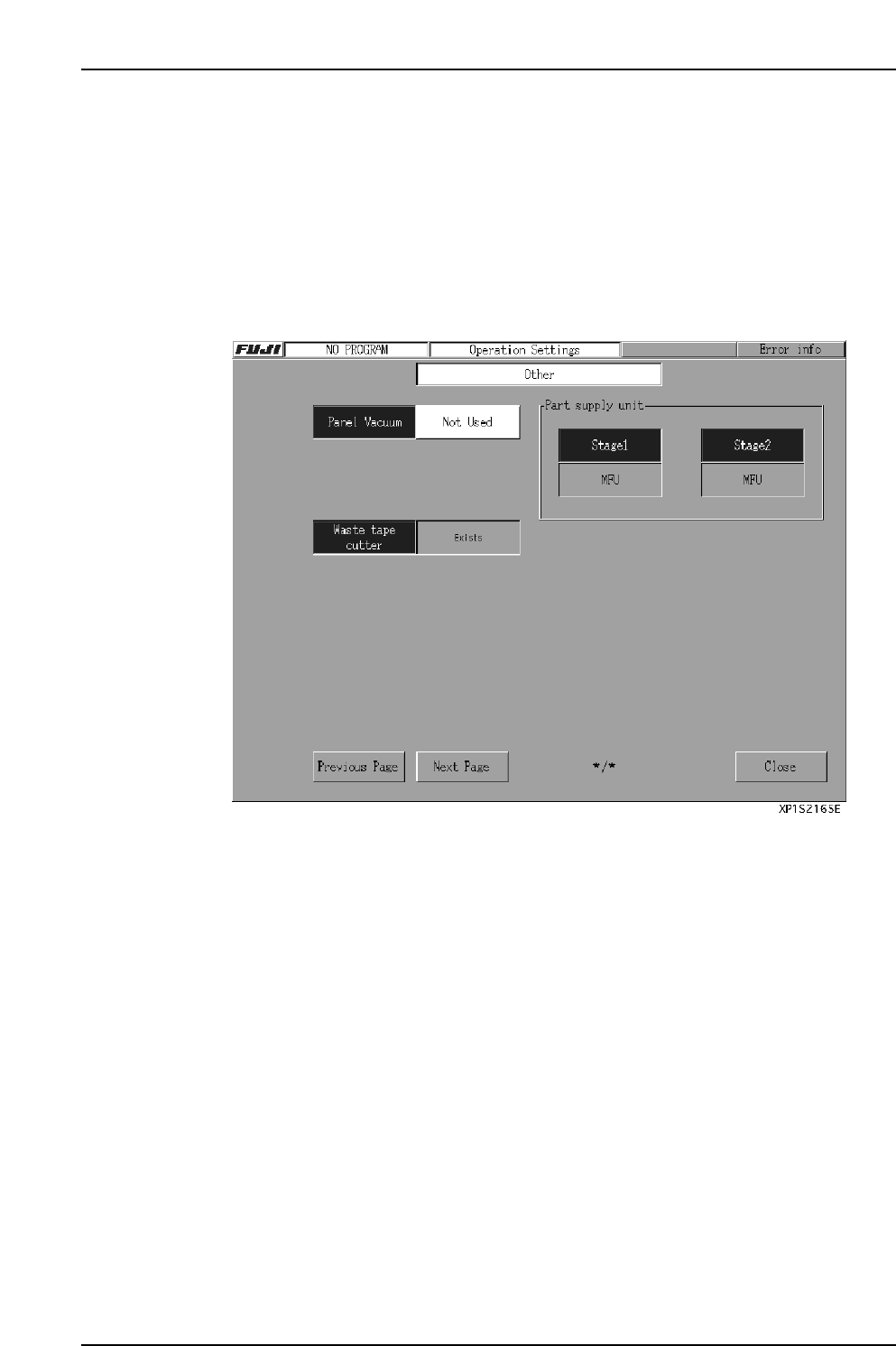
Page] button to display the [Other] screen.
3. In the textbox beside the “Panel Vacuum” item, specify whether or not the panel
vacuum function is to be used.
The default setting is “Not Used”.
4. If the operation mode is “Production”, specify (in the text box beside the “Nozzle
Size Check” item) whether or not the nozzle size check is to occur.
The default setting is “Not Executed”.
5. The current machine configuration also displays on this page.
• Indicates whether or not the waste tape cutter is present.
• Indicates whether or not the part pickup unit is present.
The display content changes as follows, depending on the part pickup unit
mounting status.
[MFU] : MFU is present.
[None] : No part supply unit is present at one of the sides.
[Fixed Device] : Fixed feeder table is being used.
Part 2 Chapter 2 Settings Prior to Start Production
Edition 2.0 2-2-10 XP-142E System Reference
2.2 Signal Tower Settings
(ESR0224b)
Signal tower lamp ON / BLINKING settings can be specified from the machine menu.
Procedure
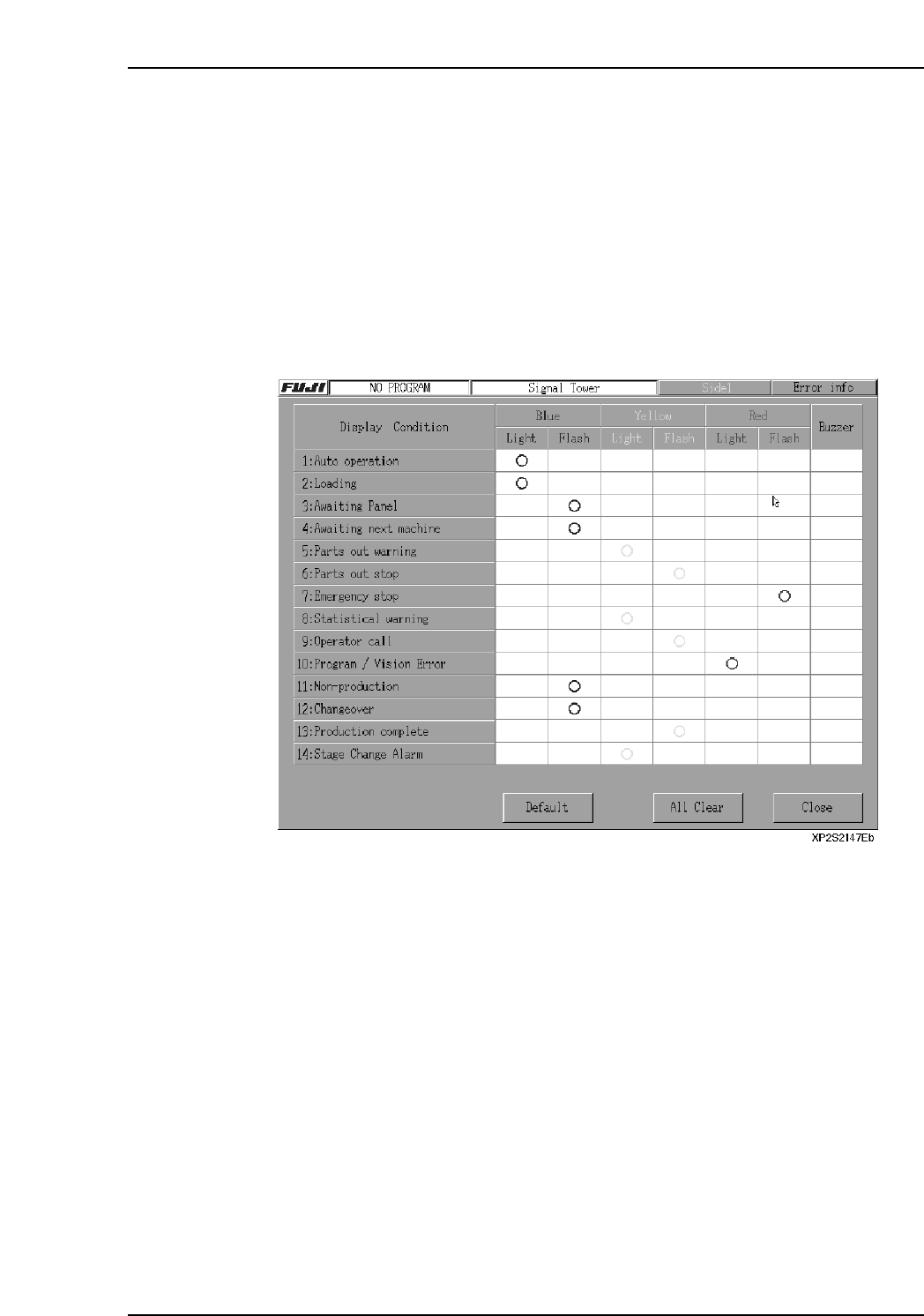
1. At the [Main] screen, press [Maintenance B] then [Signal Tower] to display the
[Signal Tower] screen.
2. Specify the signal tower color, lamp status (on/blinking), and buzzer, etc., settings
for each item. “O” marks indicate the specified settings.
3. After verifying that the settings are correct, press [Close] to end the setting
operation.
Note: Item 14: “Stage Change Alarm” is option.
Part 2 Chapter 2 Settings Prior to Start Production
Edition 2.0 2-2-11 XP-142E System Reference