XP-142E System Reference-SYS-XP142-2.0E.pdf.pdf - 第70页
Part 2 Chapter 3 Changeover Edition 2.0 2-3-16 XP-142E System Reference 3.8 Local V erify Function (Optional) This a parts verification function which prevents the wrong parts from being set, and it minimizes defective p…
Part 2 Chapter 3 Changeover
Edition 2.0 2-3-15 XP-142E System Reference
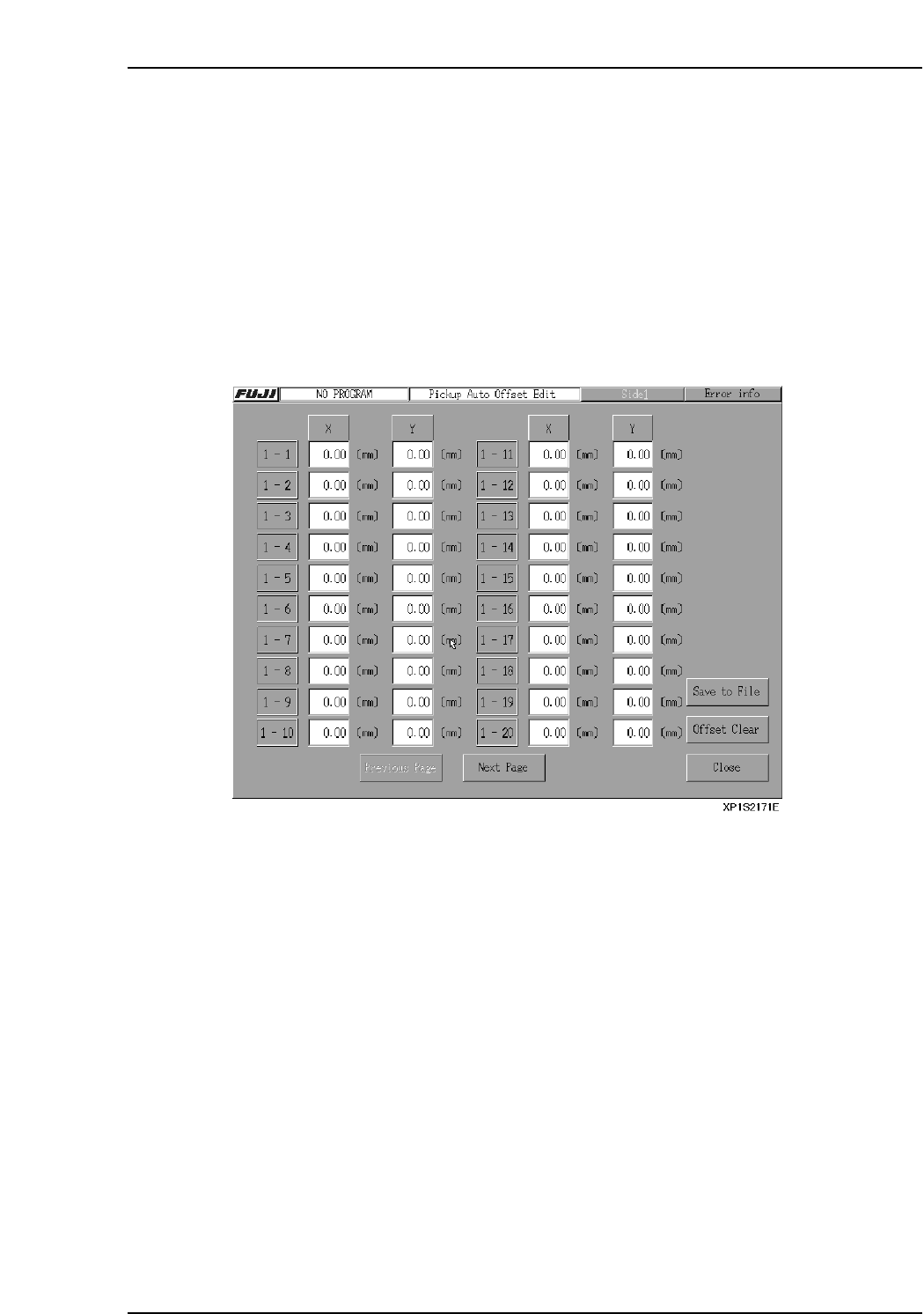
3.7 Automatic Offsetting of Pickup Position
For reasons such as variation in part position and nozzle bend, a part may not be
centered on the nozzle when picked up. The machine has a function that can be used to
automatically offset X- and Y- pickup positions to stabilize pickup.
If the part data item [Pick-up Auto Offset] is set to [0: Yes], then pickup position offsets
are calculated based on vision processing results, and subsequent pickups of the same
part are automatically offset.
Pickup Auto Offset Edit
The offset distance can been seen and edited at the [Pickup Auto Offset Edit] screen.
At the [Production] screen, select [Pickup Auto Offset] to open the [Pickup Auto Offset
Edit] screen. The commands at this screen can be used to see and edit the offsets.
[Close] button
Select this button to exit the [Pickup Auto Offset Edit] screen. A dialog will then appear
reminding you that the offsets will be saved.
[Previous Page] button
Select this button to return the display to the previous page.
[Next Page] button
Select this button to advance the display to the next page.
[Save to File] button
Select this button to save all pickup offset data to an MS Excel format file.
Notes:
• If a pickup offset data file already exists on the floppy disk, an overwrite confirmation dialog
appears.
• If a pickup offset data file already exists on the floppy disk and the file is protected, an error
message will appear.
[Offset Clear] button
Selecting this button will reset all of the offsets to 0.
When this button is selected, a confirmation dialog appears before the offsets are reset.
Part 2 Chapter 3 Changeover
Edition 2.0 2-3-16 XP-142E System Reference
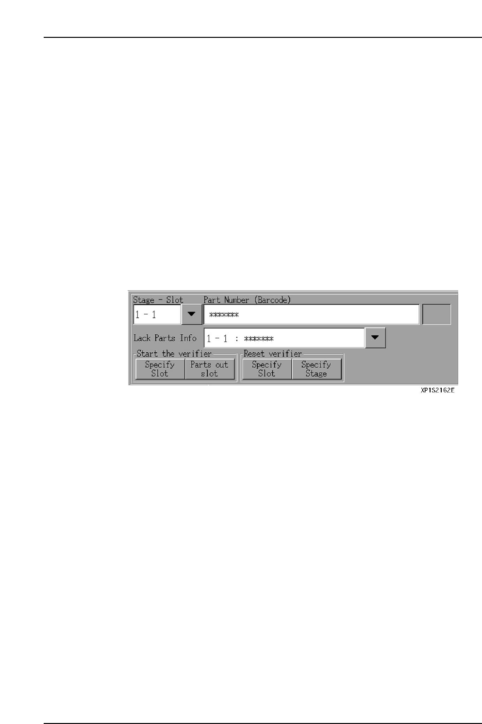
3.8 Local Verify Function (Optional)
This a parts verification function which prevents the wrong parts from being set, and it
minimizes defective panels and reject parts.
Parts Verification Procedure
The following 2 part barcodes are compared by an infrared barcode reader, with an
“OK” result being issued if the parts match.
• Part ID indicated on each reel’s barcode
• Part ID specified by the part data’s “barcode” item
Note: If the “barcode” item is not entered in the part data, then the “Part Number” is used for
the comparison.
The local verify function occurs in the following steps.
1. [Verify Start] button is pressed at the automatic operation screen.
2. Display of parts specified for barcode reading.
3. Reading of reel barcodes for specified parts.
4. After all reel barcode readings have been checked against the part data, automatic
operation is enabled.
Part 2 Chapter 3 Changeover
Edition 2.0 2-3-17 XP-142E System Reference
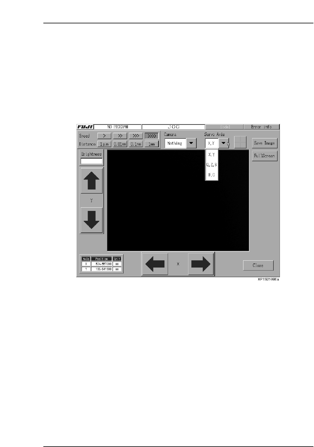
3.9 Inching
(ESR0219c)
3.9.1 Moving an Axis with the Inching Keys
The inching keys on the touch screen can be used to move each axis manually. Inching
can be performed at any time except under the following conditions:
• When the machine is in START ready status
• During operation
• Before the cause of an emergency stop has been cleared
• When the inching screen is not displayed.
The axis where inching is to occur is selected at the following screen.
Note: The screen shown above is the inching screen used for the following command sequence:
[Main], [Maintenance A], [JOG].
Procedure
1. At the [Main] screen, press [Maintenance A] then [JOG] to display the inching
screen.
2. Press the [▼] servo axis selection button to select the axis where movement is
desired, then press [Change].
3. To move the axis (inching), press the arrow buttons for the axis in question.