XP-142E System Reference-SYS-XP142-2.0E.pdf.pdf - 第167页
Production Quantity The production quantity can be specified here. If 0 is specified, then the [Scheduled Panels] setting (in the Operation Settings screen) is enabled. (0 - 65000) Pass Mode Specified during Pass mode op…
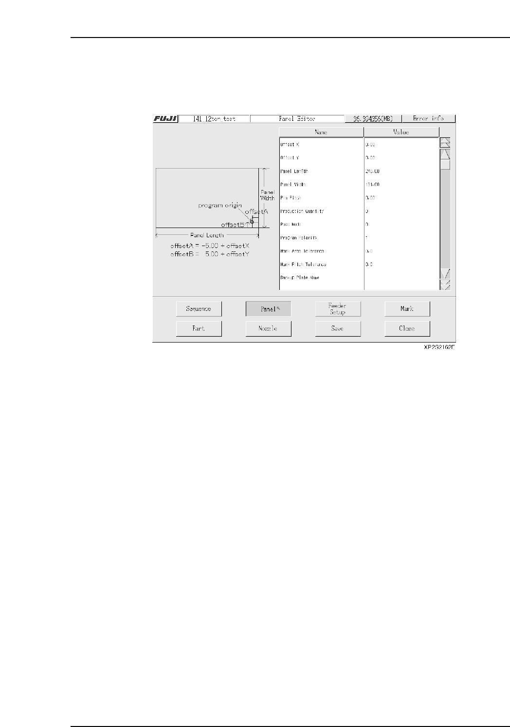
3.3 Panel Editing
(ESR0705g)
The Panel data editor is used to specify information about the panel on which parts are
to be placed.
Setting Item Explanations
Offset X
If a sequence coordinate is entered relative to a reference point other than the Fuji
program’s origin point (-5 mm in X-direction, or +5 mm in Y-direction, measured from
panel’s bottom right corner), an X-offset value must be entered, representing the distance
from the Fuji program’s origin point to the reference point which was used.
(-600.00 mm ~ 600.00 mm)
Offset Y
If a sequence coordinate is entered relative to a reference point other than the Fuji
program’s origin point (-5 mm in X-direction, or +5 mm in Y-direction, measured from
panel’s bottom right corner), an Y-offset value must be entered, representing the distance
from the Fuji program’s origin point to the reference point which was used.
(-600.00 mm ~ 600.00 mm)
Panel Size X
Specifies the panel’s X-direction size. (80.00 mm ~ 457.00 mm)
Panel Size Y
Specifies the panel’s Y-direction size. (50.00 mm ~ 356.00 mm)
Pin Pitch
Enter the distance between the reference hole (pin) and the secondary hole (pin).
(0.00 ~ 457.00)
Part 3 Chapter 3 Editor
Edition 2.0 3-3-11 XP-142E System Reference

Production Quantity
The production quantity can be specified here. If 0 is specified, then the [Scheduled
Panels] setting (in the Operation Settings screen) is enabled. (0 - 65000)
Pass Mode
Specified during Pass mode operations. When specified, the panels pass through the
machine without parts being mounted (conveyor operation only).
0: No Pass Not to perform pass through operation
1: Pass Perform pass through operation
Program Polarity
This setting determines whether or not the “standardized program method” (polarity
function) is used.
0: No Not to use program polarity function
(This setting currently is not supported. Production will not start if this is
set to “0”.)
1: Yes Use program polarity function
Refer to “Polarity function” for more detail.
Mark Identification Error Check Area
Specifies the tolerance for the area where checks for mark identification errors occur.
(0.0 ~ 10.0)
The identification check is not completed if the value is set to 0.0.
Mark Pitch Shift Tolerance
Specifies the tolerance range for shifts in the mark pitch. (0.0 ~ 10.0)
The pitch check is not completed if the value is set to 0.0.
Backup Plate Name (Presently not supported)
Specifies the name of the backup plate.
Soft Landing Speed
Specifies the Z-axis moving speed (as a % value). (0.0 % ~ 10.0 %)
[Ex] Speed = 75 [mm/sec] x setting value / 10
Part 3 Chapter 3 Editor
Edition 2.0 3-3-12 XP-142E System Reference
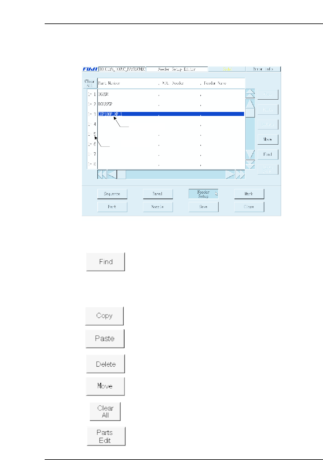
3.4 Editing Feeder Setup Data
(ESR0706e)
The Feeder Setup Editor is used to specify which part is to be set in which slot.
Operation Button Explanations
Searches the feeder setup for a specified character string in the feeder
setup.
The following buttons apply to the line which has been selected in the selection area at
the left side of the screen.
Copies the selected line to the clipboard.
Pastes the clipboard data below the selected line.
Deletes the selected line.
Moves feeder positions, and exchanges feeders.
Cancels all selections.
Edits (at part editor screen) the part to be placed at the selected line.
2 0, F, -99.59, 0.00, 0,
Data input line
Selecting area
XP2S2163Ea
Part 3 Chapter 3 Editor
Edition 2.0 3-3-13 XP-142E System Reference