XP-142E System Reference-SYS-XP142-2.0E.pdf.pdf - 第161页
3.2.1 Position Offset Use this function to offset coordinate settings for single boards. Board Number Specify the number of the board whose coordinates will be offset. All: Position offset will apply to all boards on a p…
Terminate (Presently not supported)
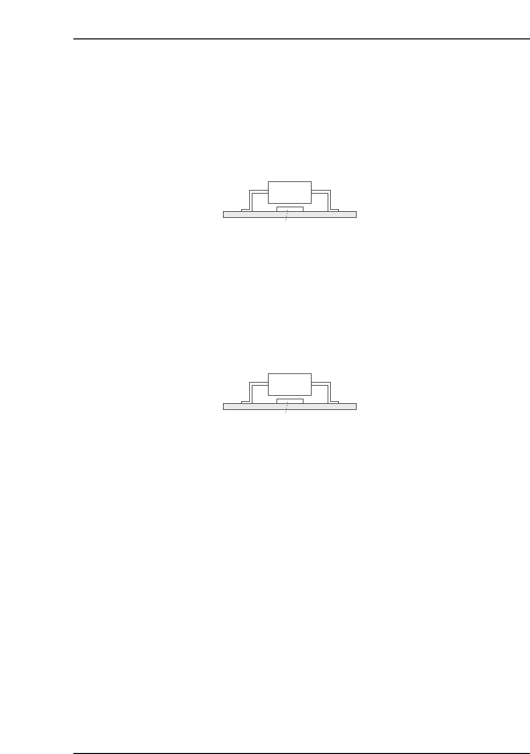
In cases where part placement is occurring as shown in the illustration below, a 3216 part
placing error occurs, and the 3216 part cannot be placed if the SOIC part is placed first.
To avoid this problem, set the “Terminate” item of the SOIC placing sequence to “1”
(terminate sequence enabled) so that the SOIC part will not be placed until all other
placing sequences are completed.
As a result, even when an error occurs at the previous sequence, the part for the next
sequence will not be placed.
0: No terminate sequence 1: Execute terminate sequence
Place Before
Enter the comment for the placement sequence which is to occur later (max. 256
characters). If an error occurs at the 3216 part placement when placing parts as shown in
the illustration below, it will no longer be possible to place the 3216 part if the SOIC part
is placed first. Entering the SOIC sequence comment in this 3216 placement sequence
textbox ensures that the SOIC part will not be placed until after the 3216 part has been
placed.
Comment
Up to 256 characters can be used for the sequence comment input. In order to specify a
“Place Before” sequence comment, unique sequence comments must be specified for
each board. When a “Place Before” entry is made, there must be other parts with the
same sequence comment on that board.
Panel
SOIC
3216
MCSX313E
Panel
SOIC
3216
MCSX313E
Part 3 Chapter 3 Editor
Edition 2.0 3-3-5 XP-142E System Reference
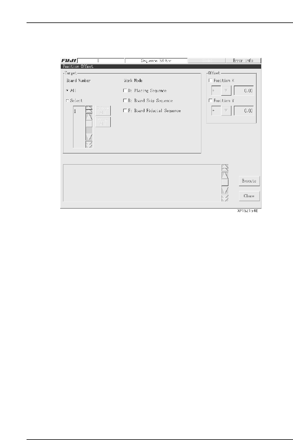
3.2.1 Position Offset
Use this function to offset coordinate settings for single boards.
Board Number
Specify the number of the board whose coordinates will be offset.
All: Position offset will apply to all boards on a panel.
Select: Specify single boards whose position will be offset.
Work Mode
Specify the type of coordinate to offset.
D: Part placement coordinates
B: Board skip mark coordinates
F: Board fiducial mark coordinates
Offset
Specify the offset axis, direction (+ or –), and distance.
(Input range: 0.00 - 650.00 mm)
Execute A confirmation message is displayed.
[Yes]: Execute the offset and return to the [Position Offset] screen.
[No]: Return to the [Position Offset] screen without executing the offset.
[Close]: Close the [Position Offset] screen to return to the [Sequence Editor]
screen.
Note: The above offset conditions are saved when an offset is executed successfully.
Part 3 Chapter 3 Editor
Edition 2.0 3-3-6 XP-142E System Reference
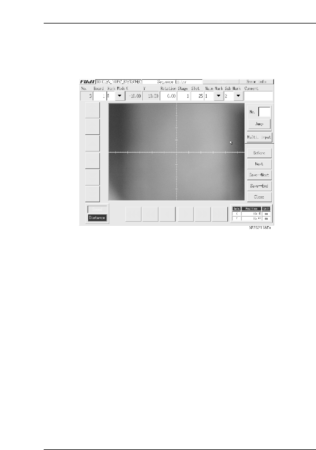
3.2.2 Teaching
Press [Teach] at the sequence data editing window to display the image acquired from
the mark camera at the touch screen. Teaching is performed by actually moving the
machine axes to the desired positions, with these positions becoming the sequence data’s
X and Y coordinates.
When the above window displays, all fiducial marks are identified and coordinate
correction values are obtained. These coordinate correction values are used to convert
the machine X,Y coordinates to panel X,Y coordinates. Once these coordinate correction
values are obtained, they are saved until program editing is completed, or until the F-
mark sequence is changed. When in the Overwrite mode, the servo axis is positioned in
accordance with the specified sequence data’s X,Y coordinates.
Part 3 Chapter 3 Editor
Edition 2.0 3-3-7 XP-142E System Reference