XP-142E System Reference-SYS-XP142-2.0E.pdf.pdf - 第206页
10. When the [Select Image] dialog box displays, select [Image Capture], then press [Next]. Operation Button Explanations Image capture Browse Gain An image is captured by the camera. Opens a file selection dialog box fr…
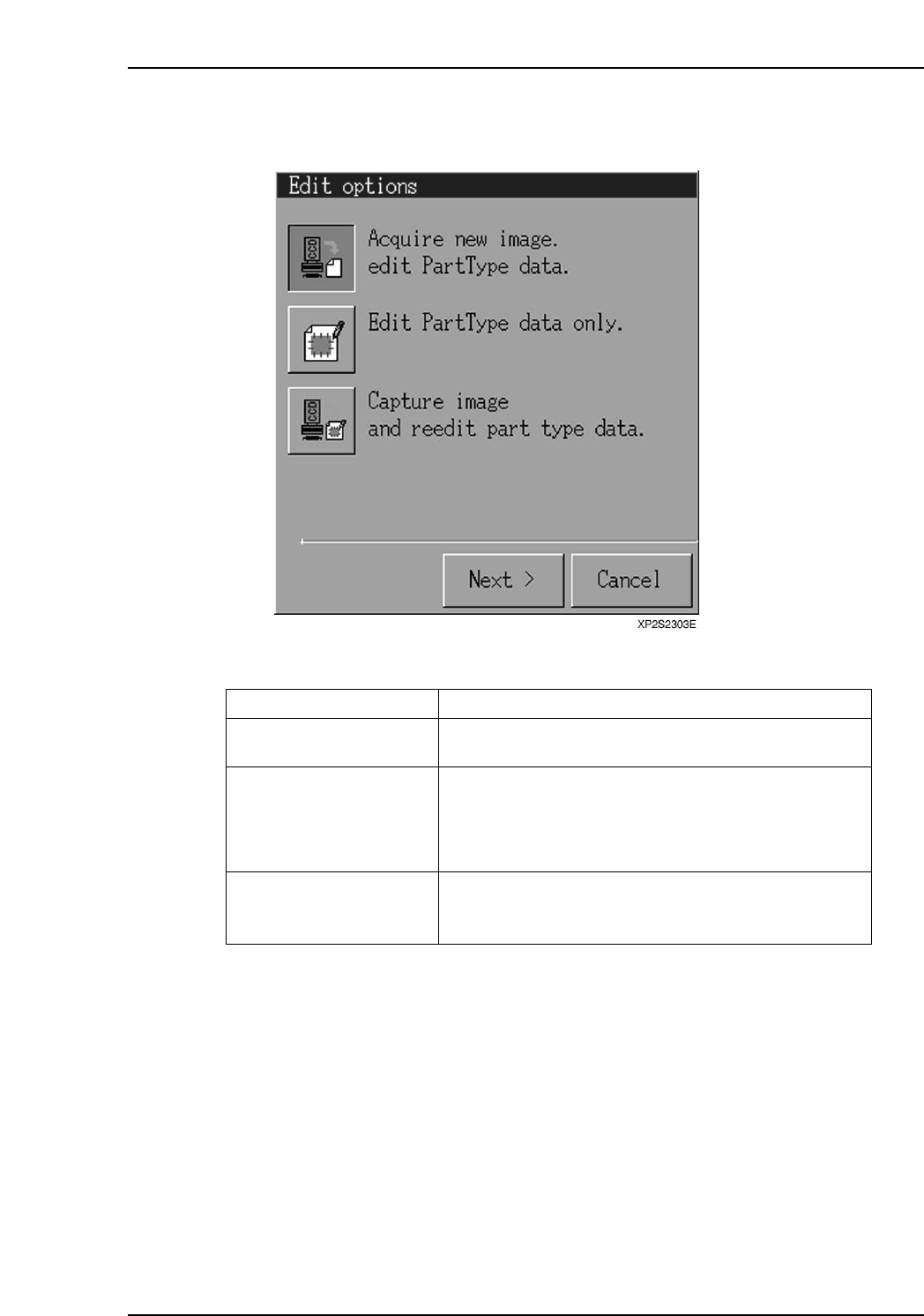
9. Press [Template Editor] to open the [Edit Options] dialog box. Select "Acquire
new image and edit PartType data", then press [Next].
Operation Button Explanations
Acquire new image and edit
PartType data.
Edit PartType data only.
Capture image and reedit
part type data.
Creates a new template based on the acquired image or
the specified image file.
Re-edits an existing template using a previously created
image file. This function is only operative when there is
an image file with the same name as the PartTypeName
or PartNumber being edited, when editable template data
exists, or when no template data exists.
Re-edits a template based on the acquired image or the
specified image file. This function is only operative
when editable template data exists.
XP1S2316E
Display Function
Part 4 Chapter 2 Creating a Template From Existing Part Data
Edition 2.0 4-2-3 XP-142E System Reference
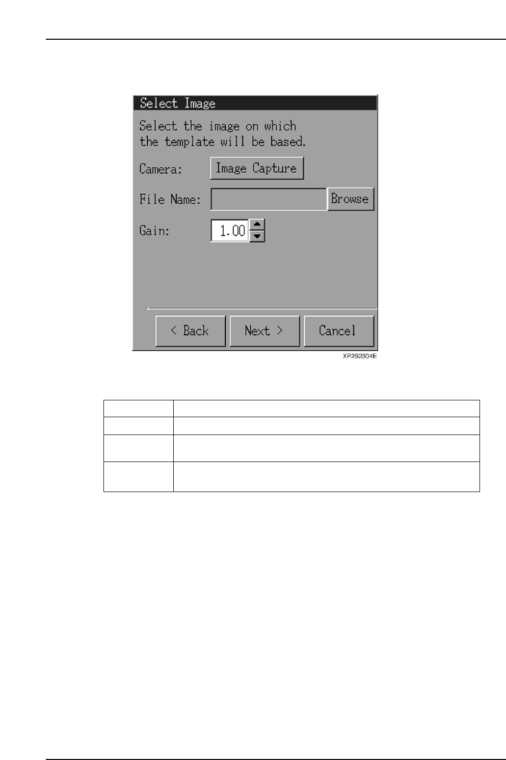
10. When the [Select Image] dialog box displays, select [Image Capture], then press
[Next].
Operation Button Explanations
Image capture
Browse
Gain
An image is captured by the camera.
Opens a file selection dialog box from which the desired image file can
be selected.
Changes the screen brightness in a virtual manner. The range is 0 ~ 255,
and the default setting is 1.00.
XP1S2317E
Display Function
Part 4 Chapter 2 Creating a Template From Existing Part Data
Edition 2.0 4-2-4 XP-142E System Reference
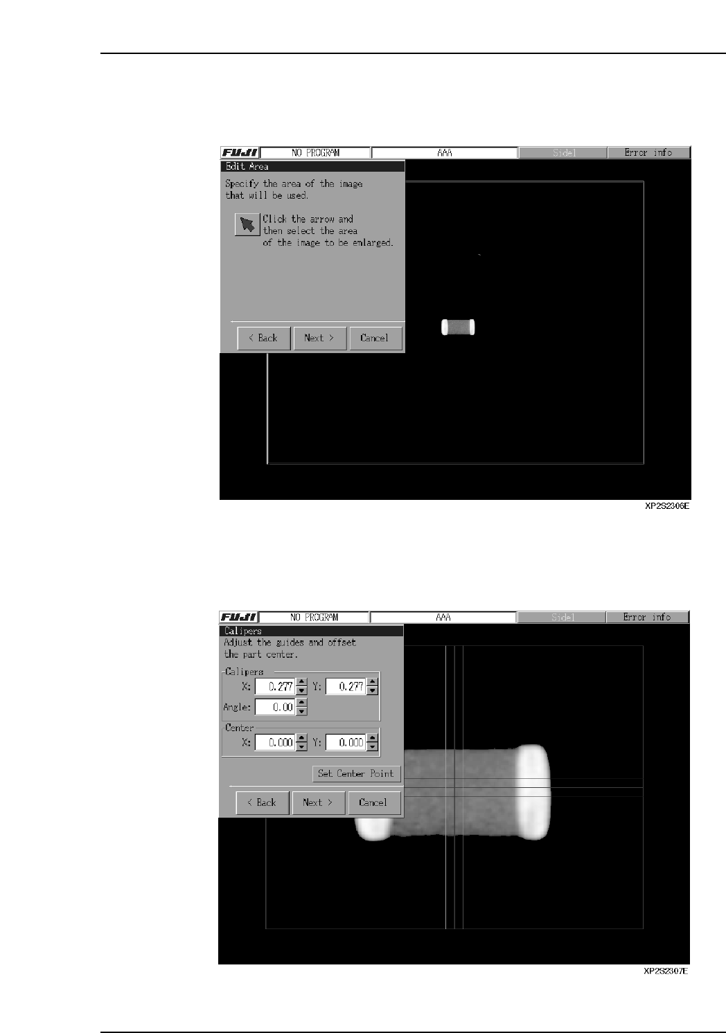
11. An image of the picked up part is then captured. Click the arrow button at the
[Edit Area] dialog box, drag the part image to the desired position, then press
[Next].
12. The lines which then display can be moved by dragging them, by entering the
coordinates in the [Calipers] textbox, or by pressing the arrow buttons beside the
textbox. Align the red lines with the part center by aligning the blue and green
lines with the part's top, bottom, left, and right sides. Press [Set Center Point] to
correct the image position, then press [Next].
Part 4 Chapter 2 Creating a Template From Existing Part Data
Edition 2.0 4-2-5 XP-142E System Reference