XP-142E System Reference-SYS-XP142-2.0E.pdf.pdf - 第210页
21. Specify the camera position, then press [Next]. 22. Press [Close] to end the editing operation. Part 4 Chapter 2 Creating a T emplate From Existing Part Data Edition 2.0 4-2-8 XP-142E System Reference
16.
Select the inspection line display mode, then draw seek lines at the
required points. After drawing the seek lines, repeat the edge position
correction operation (see above).
17.
Select the image position correction function to correct the image
center position and angle.
18.
Select "Close".
19. Select "End Generation" at the dialog box.
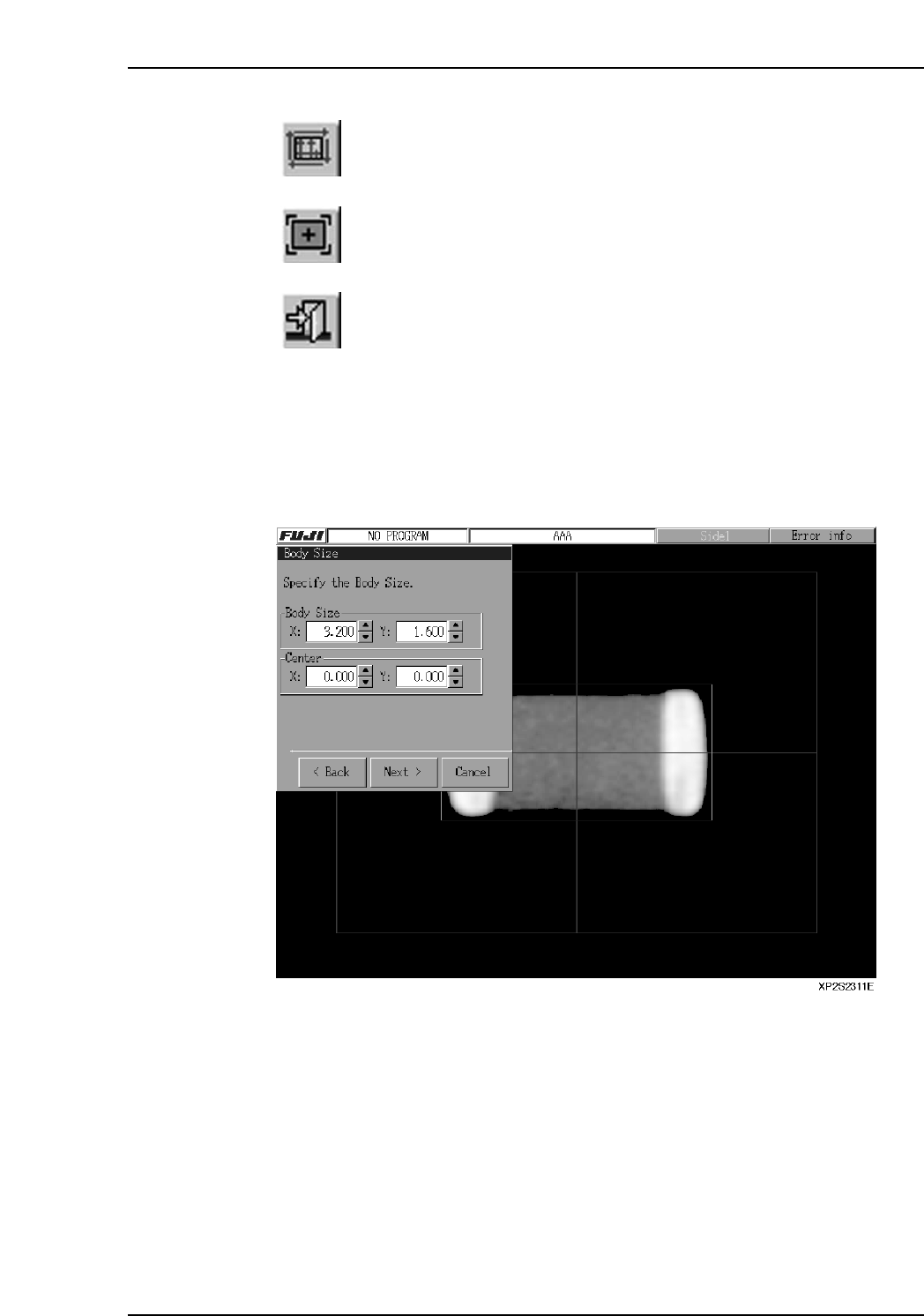
20. Displayed lines can be moved by dragging them, by entering the coordinates in
the [Body Size] textbox, or by pressing the arrow buttons beside the textbox. Align
the blue and green lines with the part's top, bottom, left, and right sides, then press
[Next].
Part 4 Chapter 2 Creating a Template From Existing Part Data
Edition 2.0 4-2-7 XP-142E System Reference
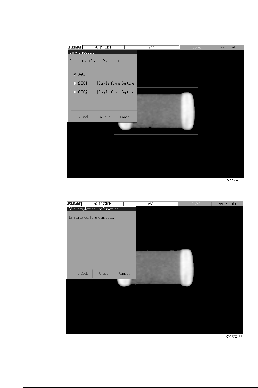
21. Specify the camera position, then press [Next].
22. Press [Close] to end the editing operation.
Part 4 Chapter 2 Creating a Template From Existing Part Data
Edition 2.0 4-2-8 XP-142E System Reference
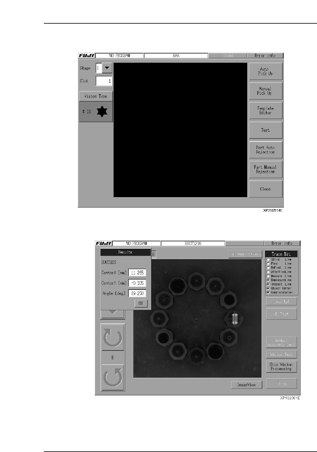
23. Press [Test].
24. When "Vision Processing" is selected, the test occurs, and the results display.
Part 4 Chapter 2 Creating a Template From Existing Part Data
Edition 2.0 4-2-9 XP-142E System Reference