XP-142E System Reference-SYS-XP142-2.0E.pdf.pdf - 第66页
Part 2 Chapter 3 Changeover Edition 2.0 2-3-12 XP-142E System Reference 3.5.3 Nozzle Center Measurement Nozzle center measurements occur using the parts camera to perform vision processing on a gauge chip part to determi…
3. Exchange the nozzles on the machine in accordance with the [Machine nozzles]
list.
4. After the nozzle change, press the [Size Check] button.
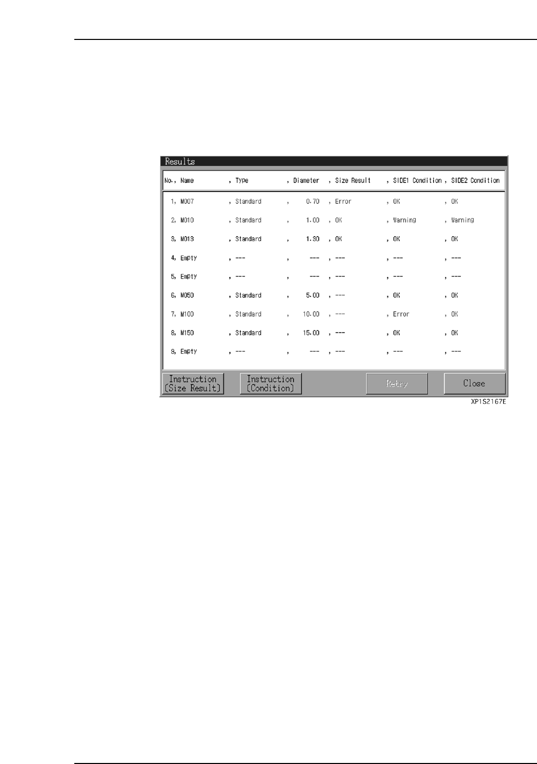
The following items are checked:
• Nozzle size (Size Result)
• Nozzle brightness (Condition)
After the above items have been checked, the “Results” dialog box displays.
5. Verify that no warning or error conditions exist at the “Size Result” and
“Condition” items. If an error exists, check the nozzle, etc., in accordance with the
“Size Result” and “Condition” instructions, and correct the error cause.
Perform another “Size Check” and verify that there are no errors.
Note: As the nozzle brightness measurement result is applied to vision processing during
production, be sure that there is no error.
Part 2 Chapter 3 Changeover
Edition 2.0 2-3-11 XP-142E System Reference
Part 2 Chapter 3 Changeover
Edition 2.0 2-3-12 XP-142E System Reference
3.5.3 Nozzle Center Measurement
Nozzle center measurements occur using the parts camera to perform vision processing
on a gauge chip part to determine the nozzle holder’s rotation center.
The vector between the rotation center and the mark camera center is measured.
(This measurement can be performed for standard (ø0.4 ~ ø5.0 nozzles.)
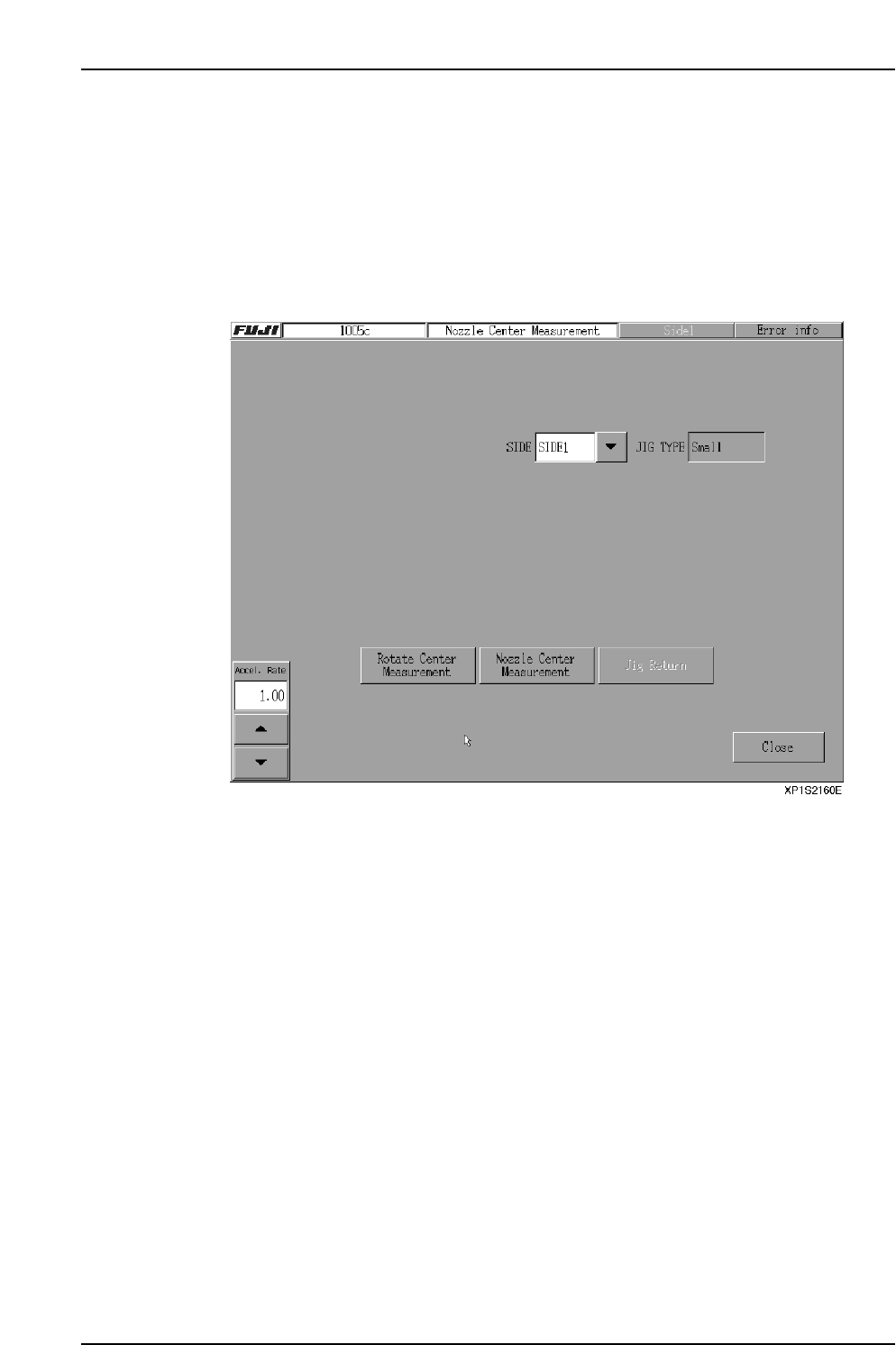
Procedure
1. At the [Main] screen, press [Production] then [Nozzle Center Measurement] to
display the screen shown below.
2. Select the Side where the measurement is to occur, then press the [Start rotation
measurement] button. Measurement occurs using the machine’s front camera if
Side 1 was selected, and the rear camera if Side 2 was selected.
Select the appropriate jig (3 types) according to the size of the mounted nozzle
(displays at the [Jig Type] area). The vector between the revolver (R-axis) and the
mark camera center is measured.
3. When the rotation center measurement is completed, press the [Nozzle center
measurement] button. This measurement is performed by the same camera which
performed the rotation center measurement.
Note: As measurements are performed for each nozzle, all the nozzles should be
mounted.

3.6 Supply of Tape Parts
(ESR0221e)
The MFU is clamped to, and unclamped from, the machine by an air cylinder driven
mechanism. The Side 1 procedure is explained below, but the procedure is identical for
Side 2.
Note: This function is disabled on machines equipped with a fixed device table.
3.6.1 Changing an MFU
Clamping Procedure
1. Open the machine’s front door, then gently push the MFU into its machine
docking position.
2. At the [Main] screen, press [Manual Operation], then [STAGE1 MFU Clamp] to
display a start confirmation dialog box. Press the START switch to clamp the
MFU.
Unclamping Procedure
1. From the [Main] screen, select [Machine Operation] - [STAGE1 MFU Unclamp].
A “START confirmation” dialog box then displays.
2. Press [START] to unclamp the machine’s front-side MFU.
The following message then displays: “Work after the door of the front is opened.”
3. Open the door at the side where the MFU was unclamped, then press [OK] on the
display screen.
4. Gently pull the MFU out of the machine.
Note: Only the MFU on the side of the machine that is enabled can be removed.
3.6.2 Tape Cutter Manual Operation
1. At the [Main] screen, select [Manual Operation], then [Tape Cutter Stage1].
A confirmation dialog is displayed.
2. Push the START button to cut the feeder tape on Side 1 of the machine.
Note: This command is restricted to the control panel on the same side of the machine as
the tape cutter to be activated.
Part 2 Chapter 3 Changeover
Edition 2.0 2-3-13 XP-142E System Reference