XP-142E System Reference-SYS-XP142-2.0E.pdf.pdf - 第186页
Part 3 Chapter 3 Editor Edition 2.0 3-3-31 XP-142E System Reference Process Maximum Nozzle Diameter Specifies the maximum size of the nozzle used to handle the parts. (0.0 mm ~ 99.9 mm) Minimum Nozzle Diameter Specifies …
Setting Item Explanations
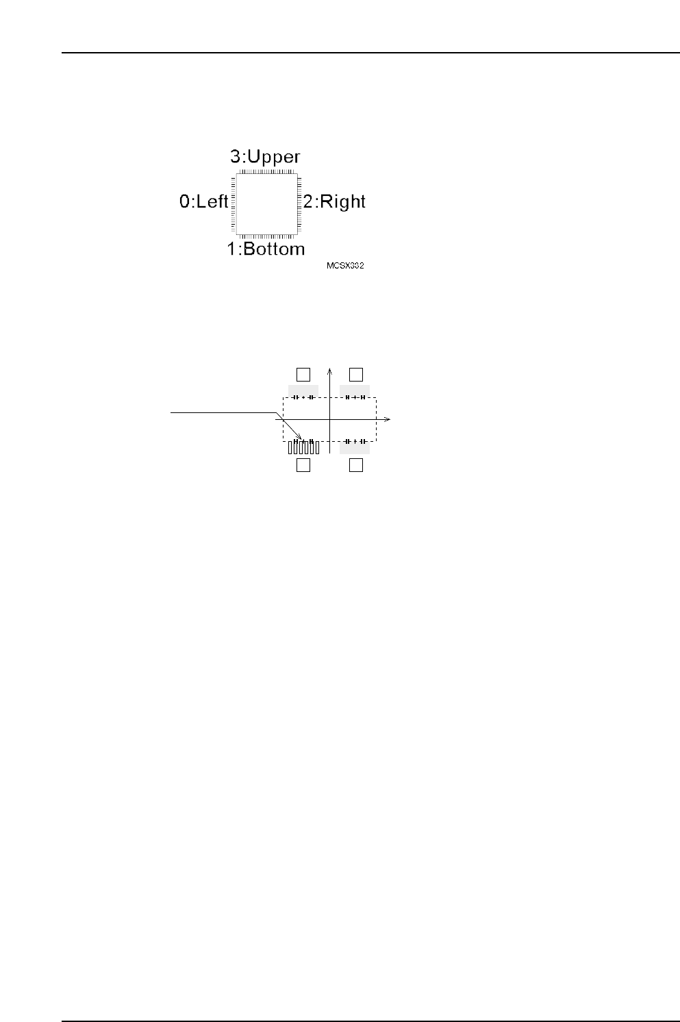
Side
Specify the body side where the element is located.
Position X, Position Y
Specify the X/Y direction position of the element center, as measured from the body
center. (-99.99 mm ~ 99.99 mm)
Lead Quantity
Specifies the number of leads in the element. (0 ~ 128)
Lead Pitch
Specifies the pitch between the leads. (0.000 mm ~ 99.999 mm)
Lead Width
Specifies the lead width. (0.000 mm ~ 99.999 mm)
Lead Length
Specifies the lead length. (0.000 mm ~ 99.999 mm)
Lead Width Tolerance (Presently not supported)
Specifies the lead width tolerance. (0.000 mm ~ 99.999 mm)
Lead Length Tolerance
Specifies the lead length tolerance. (0.000 mm ~ 99.999 mm)
If a setting of “0” is entered, the lead length tolerance will automatically be set as 30 % of
the lead length. This setting is only used with vision type 100.
Lead Center Tolerance
Enter the lead’s bend tolerance. (0.000mm ~ 99.999mm)
If a setting of “0” is entered, the lead center tolerance will automatically be set as 30% of
the lead length. This setting is only used with vision type 100.
P Pattern
This data defines how the lead image is viewed. (0 ~ 255)
When using Vision Type 100 (QF & Connector: Frontlight processing), enter a setting of
“14”. If the lead is dark and the background is light, enter a setting of “13”.
Lead element
12
43
MCSX333Ea
(PositionX, PositionY)
(0, 0)
Part 3 Chapter 3 Editor
Edition 2.0 3-3-30 XP-142E System Reference
Part 3 Chapter 3 Editor
Edition 2.0 3-3-31 XP-142E System Reference
Process
Maximum Nozzle Diameter
Specifies the maximum size of the nozzle used to handle the parts. (0.0 mm ~ 99.9 mm)
Minimum Nozzle Diameter
Specifies the minimum size of the nozzle used to handle the parts. (0.0 mm ~ 99.9 mm)
Nozzle Name
To use a specific nozzle, select it from the name list. (Max. of 15 characters.)
Pick-up Auto Offset
Specifies whether or not the automatic pickup offset function is to be used.
YES: Auto offset function is used : 0
NO: Auto offset function is not used : 1
Pick-up Point Offset X
Specify this setting in order to pick up a part at a position other than the slot’s X-
direction center. Direction”0” is the reference part direction when setting the offset. To
specify a 5mm offset to the right, enter “5”. (-12.7 mm ~ 12.7 mm)
Pick-up Point Offset Y
Specify this setting in order to pick up a part at a position other than the slot’s Y-
direction center. ”Direction 0” is the reference part direction when setting the offset. To
specify a 5mm offset in the “back” direction, enter “5”. (-12.7 mm ~ 12.7 mm)
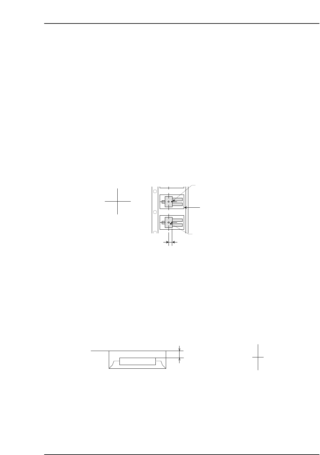
Pick-up Point Offset Z
Specify this setting in order to pick up a part at a height other than the slot’s standard
height. For example, a downward offset of 1 mm can be specified by entering “-1”.
(-12.7 mm ~ 12.7 mm)
Offset value
MCSX336E
Z (+)
Z (-)
Cavity center
(Pick-up point when Pick-up Point
Offset X is set to "0" )
Cavity
Pick-up Point Offset X
Nozzle pick-up point
X (-) X (+)
MCSX335Eb

Soft Pick Speed
Specifies a Z-axis up/down speed for part pickups which reduces the impact shock
applied to the part. The lower the setting value, the slower the Z-axis speed. A setting of
“0” is processed as “10.0”. During part pickups, the slower of the “Slow Place Speed”
and “Soft Pick Speed” settings is adopted. While the part is picked up, the “Part
Transport Speed” is also referenced, and slowest of the “Slow Place Speed”, “Soft Pick
Speed”, and “Part Transport Speed” settings is adopted. (0.0 ~ 10.0)
Part Transport Speed
Depending on the transport speed, heavier parts may shift on the nozzle between being
picked up and placed. The purpose of this setting is to prevent such shifting by
suppressing the transport speed. The speed specified here becomes the speed of all
servo motors on the machine while the heavy part is held by a nozzle. A setting of “0” is
processed as “100%”. After a part has been picked up, the slowest of the “Part Transport
Speed”, “Soft Pick Speed”, “Slow Place Speed”, and “Soft Place Speed” settings is
adopted. (0% ~ 100%)
Placing Offset X
Set the X-direction offset based on the part with direction 0 and placement orientation of
0°. (-100.00 ~ 100.00 mm)
Placing Offset Y
Set the Y-direction offset based on the part with direction 0 and placement orientation of
0°. (-100.00 ~ 100.00 mm)
Placing Offset Z
Specifies the stroke amount used when pressing a part onto a panel. A setting of “0”
results in a stroke amount of 0.3 mm. (-20.00 mm ~ 20.00 mm)
Placing Mode
This determines servo accuracy when moving to the part placement coordinates. Specify
2 to maximize placing speed. Specify 0 or 1 to maximize accuracy. (0 and 1 are available
but both settings are actually the same. )
Standard: 0 This is the low-accuracy mode for Vision Types of less than 100. For
Vision Types of 100 and higher, placement occurs in the high-accuracy
mode.
Fine-Slow: 1 Placement occurs in the high-accuracy mode.
Fine-Fast: 2 Placement occurs in the low-accuracy mode.
Slow Place Speed
Specifies the Z-axis up/down speed from part pickup to placement in order to reduce
the impact shock applied to the part. The lower the setting value, the slower the Z-axis
speed. A setting of “0” is processed as “100%”. During part pickups, the slower of the
“Slow Place Speed” and “Soft Pick Speed” settings is adopted. During part placement,
the slower of the “Slow Place Speed” and “Soft Place Speed” settings is adopted. While
the part is picked up, the “Part Transport Speed” is also referenced, and the slowest of
the “Slow Place Speed”, “Soft Place Speed”, and “Part Transport Speed” settings is
adopted. (0.0 ~ 100%)
Part 3 Chapter 3 Editor
Edition 2.0 3-3-32 XP-142E System Reference