XP-142E System Reference-SYS-XP142-2.0E.pdf.pdf - 第71页
Part 2 Chapter 3 Changeover Edition 2.0 2-3-17 XP-142E System Reference 3.9 Inching (ESR0219c) 3.9.1 Moving an Axis with the Inching Keys The inching keys on the touch screen can be used to move each axis manually. Inchi…
Part 2 Chapter 3 Changeover
Edition 2.0 2-3-16 XP-142E System Reference
3.8 Local Verify Function (Optional)
This a parts verification function which prevents the wrong parts from being set, and it
minimizes defective panels and reject parts.
Parts Verification Procedure
The following 2 part barcodes are compared by an infrared barcode reader, with an
“OK” result being issued if the parts match.
• Part ID indicated on each reel’s barcode
• Part ID specified by the part data’s “barcode” item
Note: If the “barcode” item is not entered in the part data, then the “Part Number” is used for
the comparison.
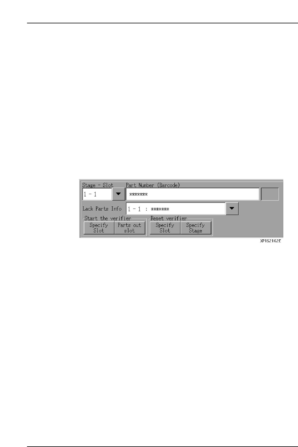
The local verify function occurs in the following steps.
1. [Verify Start] button is pressed at the automatic operation screen.
2. Display of parts specified for barcode reading.
3. Reading of reel barcodes for specified parts.
4. After all reel barcode readings have been checked against the part data, automatic
operation is enabled.
Part 2 Chapter 3 Changeover
Edition 2.0 2-3-17 XP-142E System Reference
3.9 Inching
(ESR0219c)
3.9.1 Moving an Axis with the Inching Keys
The inching keys on the touch screen can be used to move each axis manually. Inching
can be performed at any time except under the following conditions:
• When the machine is in START ready status
• During operation
• Before the cause of an emergency stop has been cleared
• When the inching screen is not displayed.
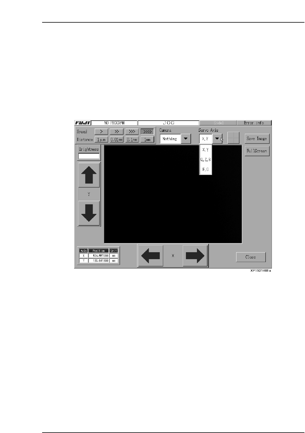
The axis where inching is to occur is selected at the following screen.
Note: The screen shown above is the inching screen used for the following command sequence:
[Main], [Maintenance A], [JOG].
Procedure
1. At the [Main] screen, press [Maintenance A] then [JOG] to display the inching
screen.
2. Press the [▼] servo axis selection button to select the axis where movement is
desired, then press [Change].
3. To move the axis (inching), press the arrow buttons for the axis in question.

Part 2 Chapter 3 Changeover
Edition 2.0 2-3-18 XP-142E System Reference
3.9.2 Changing the Inching Speed
Although inching is normally performed at low speed, the speed can be changed in
order to perform adjustments, etc.
Procedure
1. At the [Main] screen, press [Maintenance A] and then [JOG].
2. Press the “▼” servo axis selection button, select the desired servo axis.
3. At the [Setting] item, press the desired [>], [>>], [>>>], [>>>>] button to select the
desired inching speed.
3.9.3 Changing the Inching Travel Amount
Although inching is normally performed in a continuous manner, a desired inching
amount can be specified in order to perform adjustments, etc.
Procedure
1. At the [Main] screen, press [Maintenance A] then [JOG] to display the inching
screen.
2. Press the “▼” servo axis selection button, select the desired servo axis.
3. At the [Travel Amount] item, press the desired [1 µm], [0.01 mm], [0.1 mm],
[1 mm] button to select the desired inching travel amount.